As part of my upcoming glacier field work, it was decided that a camera would be a useful addition to the station, which will be installed and left unmanned for 2-3 months (see The Project) . The camera will be used to take pictures of the station and the surrounding site, so that I’ll have a record of what was happening throughout the study period. So, as an example, I can look at the pictures from a period with some interesting data and see what the weather was like, or as another example, what type of bear it was that destroyed my equipment.
The following is a DIY post on building a type of ‘nature’ camera. If anyone is actually interested in building something like this and requires more information, feel free to contact me.
Having priced commercially available units at round $2,500, and not being overly impressed with the camera hardware being used, I decided to build my own rig. My design was strongly influenced by that of another rig built by a researcher in my department, Camilo Rada. Here is the basic outline:
- Use a good quality DSLR camera (I’m using a Canon T3i).
- Use a high capacity battery that will supply sufficient power to the camera to operate over several months.
- Use a timer to control when power is supplied to the camera and when and how often pictures are taken.
- House everything in a weatherproof container.

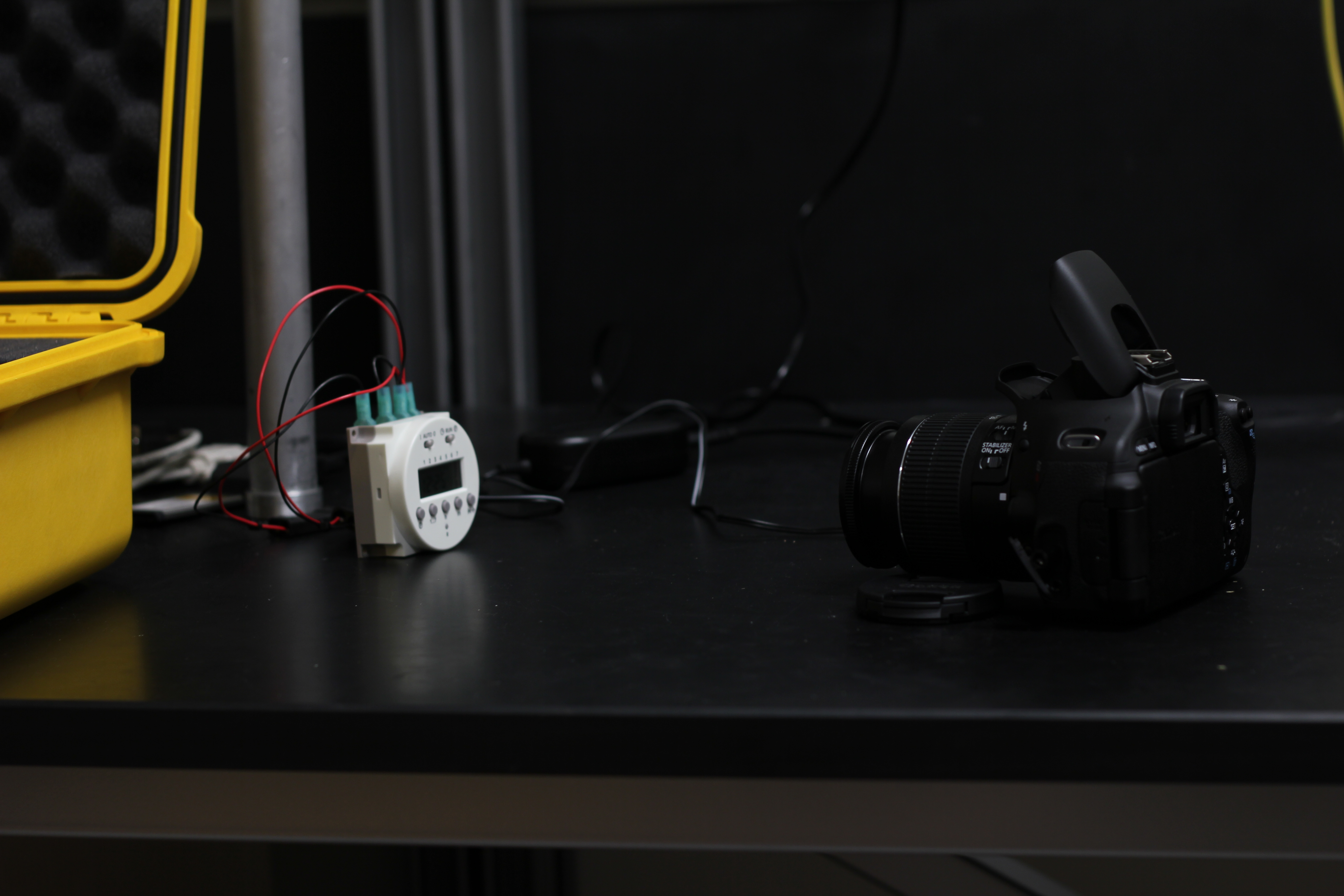
The most important component of the build is the power system. I replaced the standard camera battery with a commercially available battery adapter, which is normally used to power a camera directly from a mains socket. I wired this adapter into a DC timer, which is essentially a switch which opens and closes the power circuit at user defined times. The other end of the timer was then wired to a high capacity (10 Ah) 7.4V lithium polymer battery, originally designed for use in remote controlled aircraft.


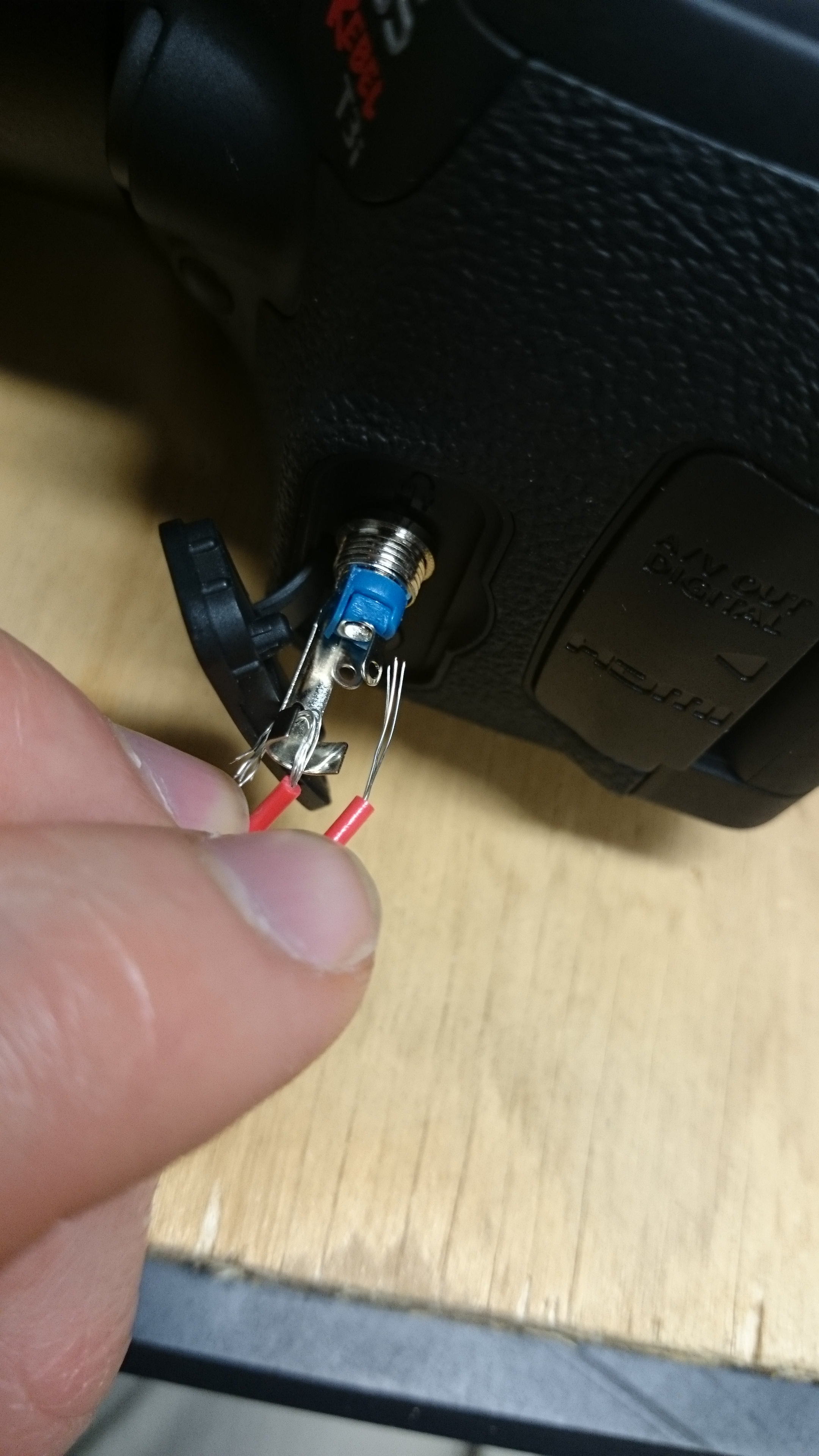
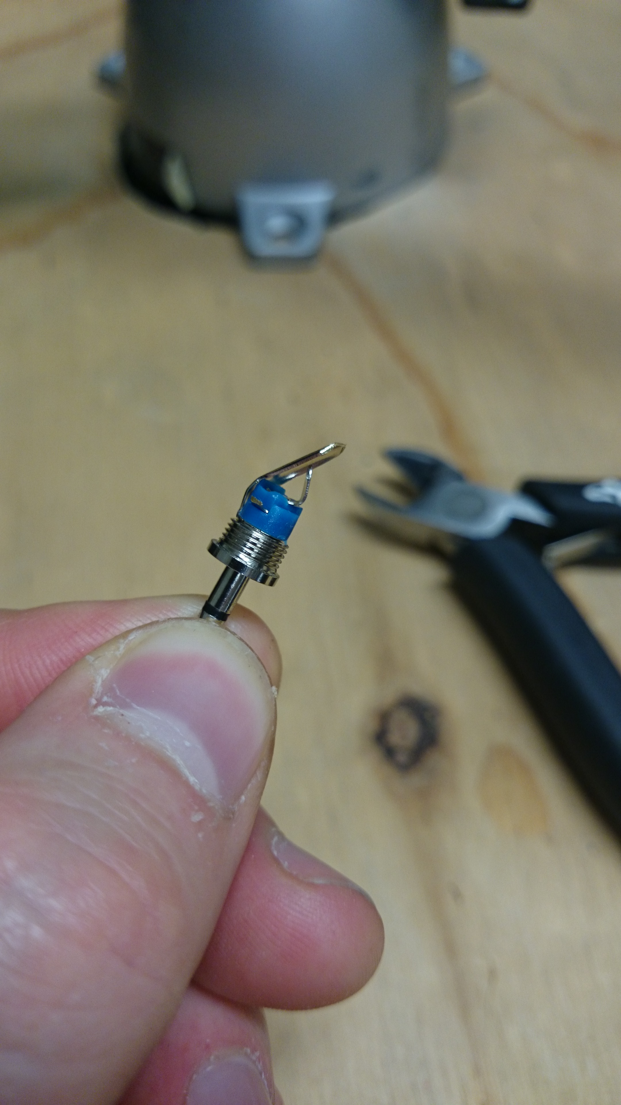
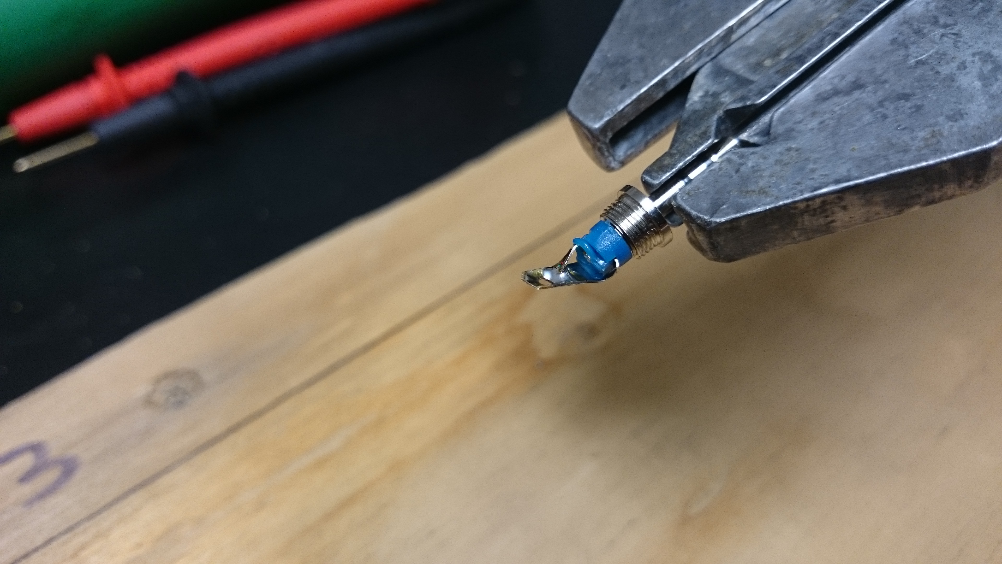
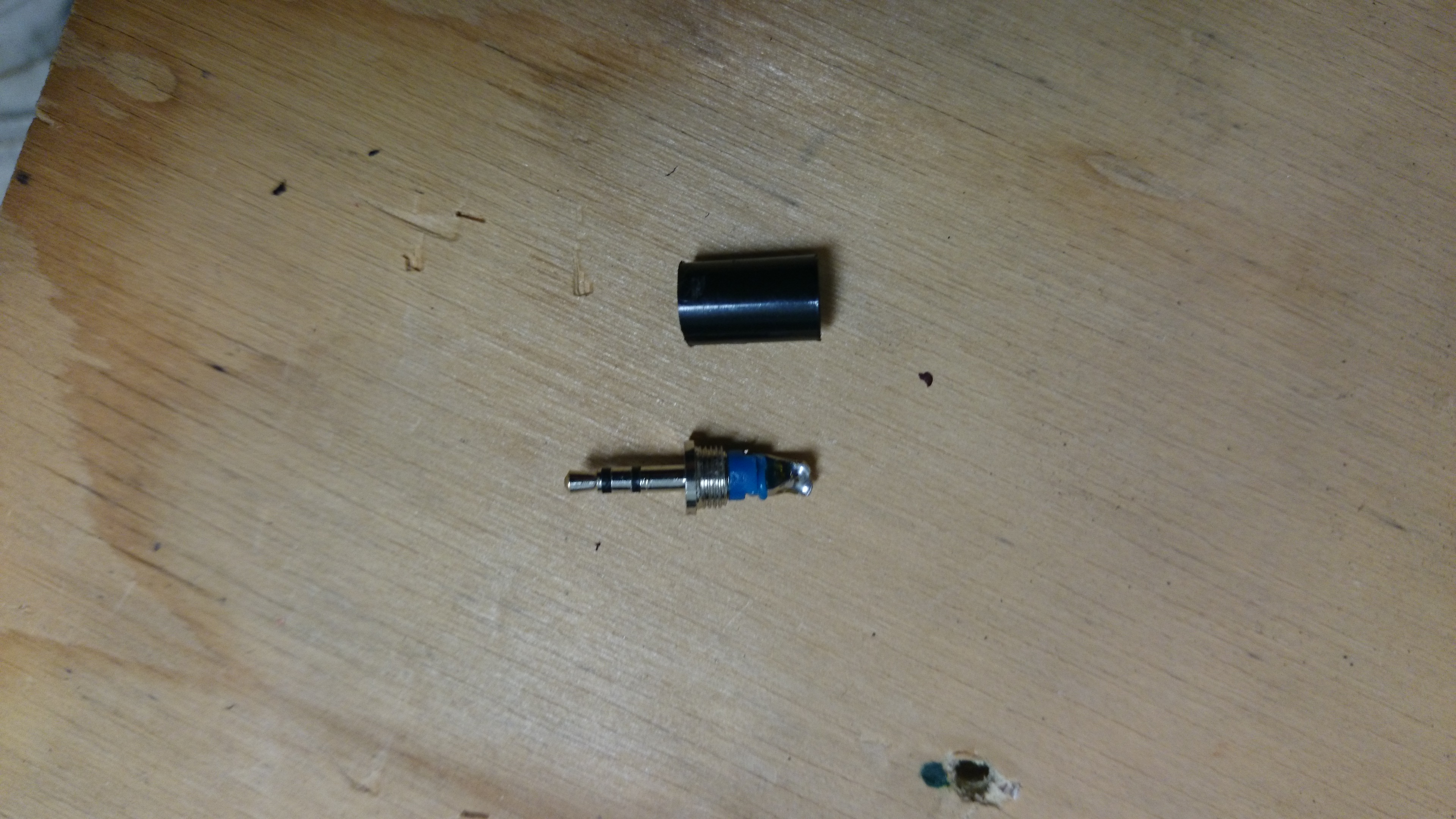
As the camera will be left to operate by itself, an automatic way of firing the shutter (taking the picture) is needed. I modified a standard 2.5mm stereo plug by shorting the outer contact (outer ring) with the inner contact (inner ring)by removing the black plastic cover and soldering the corresponding connectors together (and removing the middle connector). This plug is then inserted into the remote control port of the camera, and tells the camera that the shutter trigger is being pressed.


The timer is programmed to allow power through to the camera from the battery at set intervals, and the power switch on the camera itself is set to on. When power reaches the camera at the set times, the modified plug tells the camera that the shutter button is being pressed, and a picture is taken. After a minute, the timer shuts off power supply until the next programmed time. As for the camera settings, the mode is set to automatic (Program or P in the case of this model) so that the aperture and shutter speed will be selected automatically by the camera to suit the light conditions. The camera should be focused by the user during set up to suit the required view, and then the focus should be set to manual to prevent the camera from changing the focus during operation.


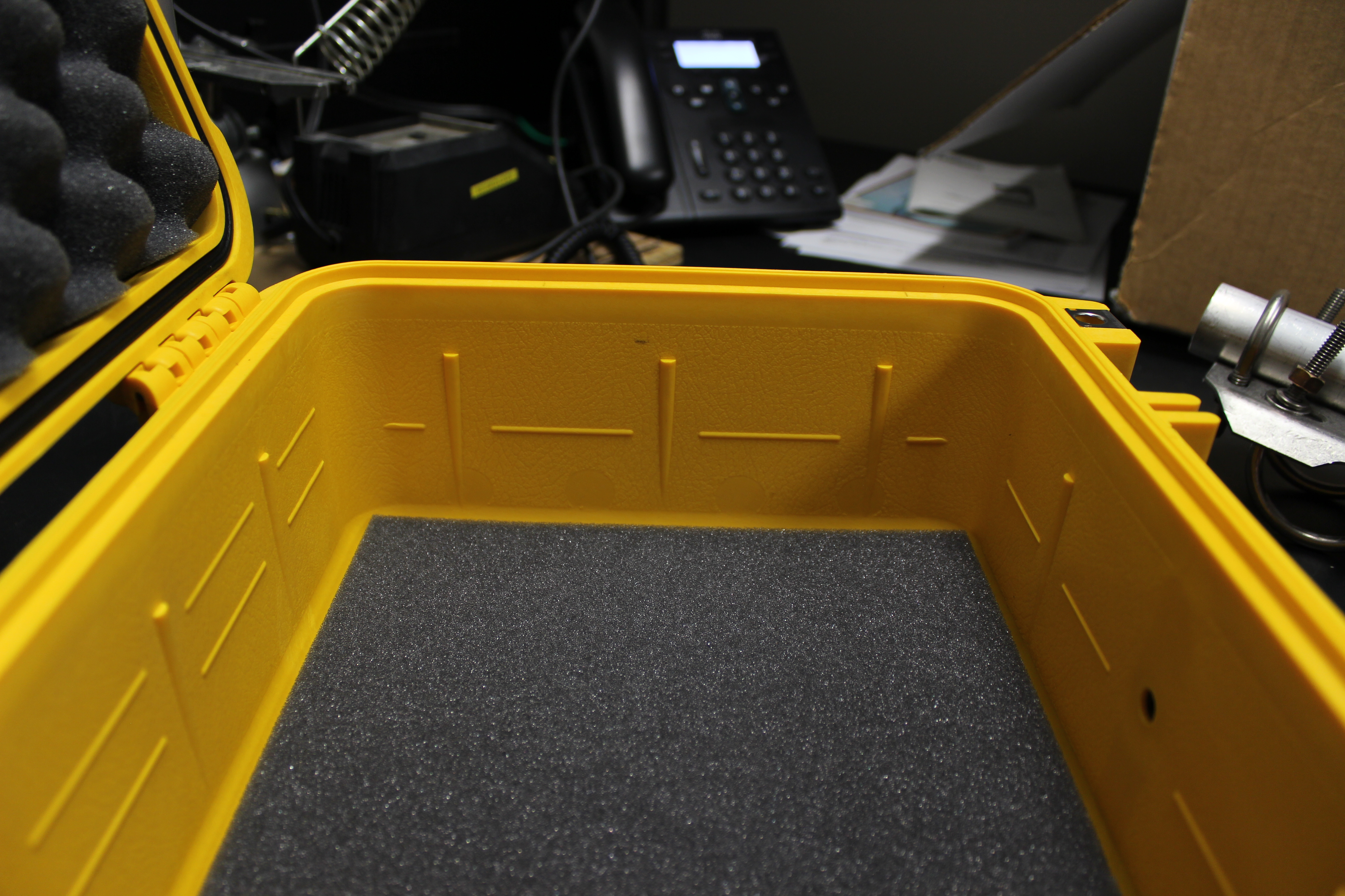
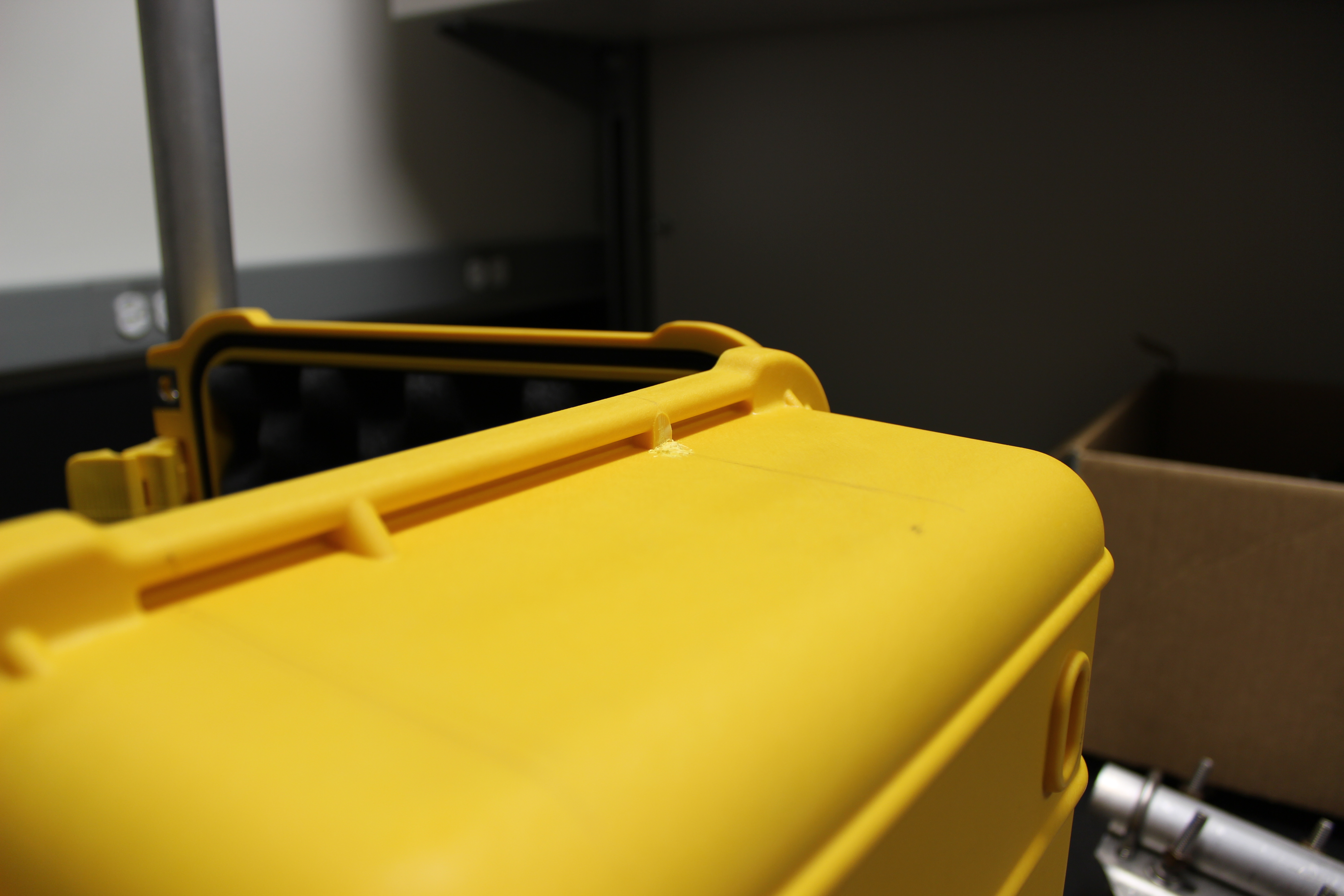
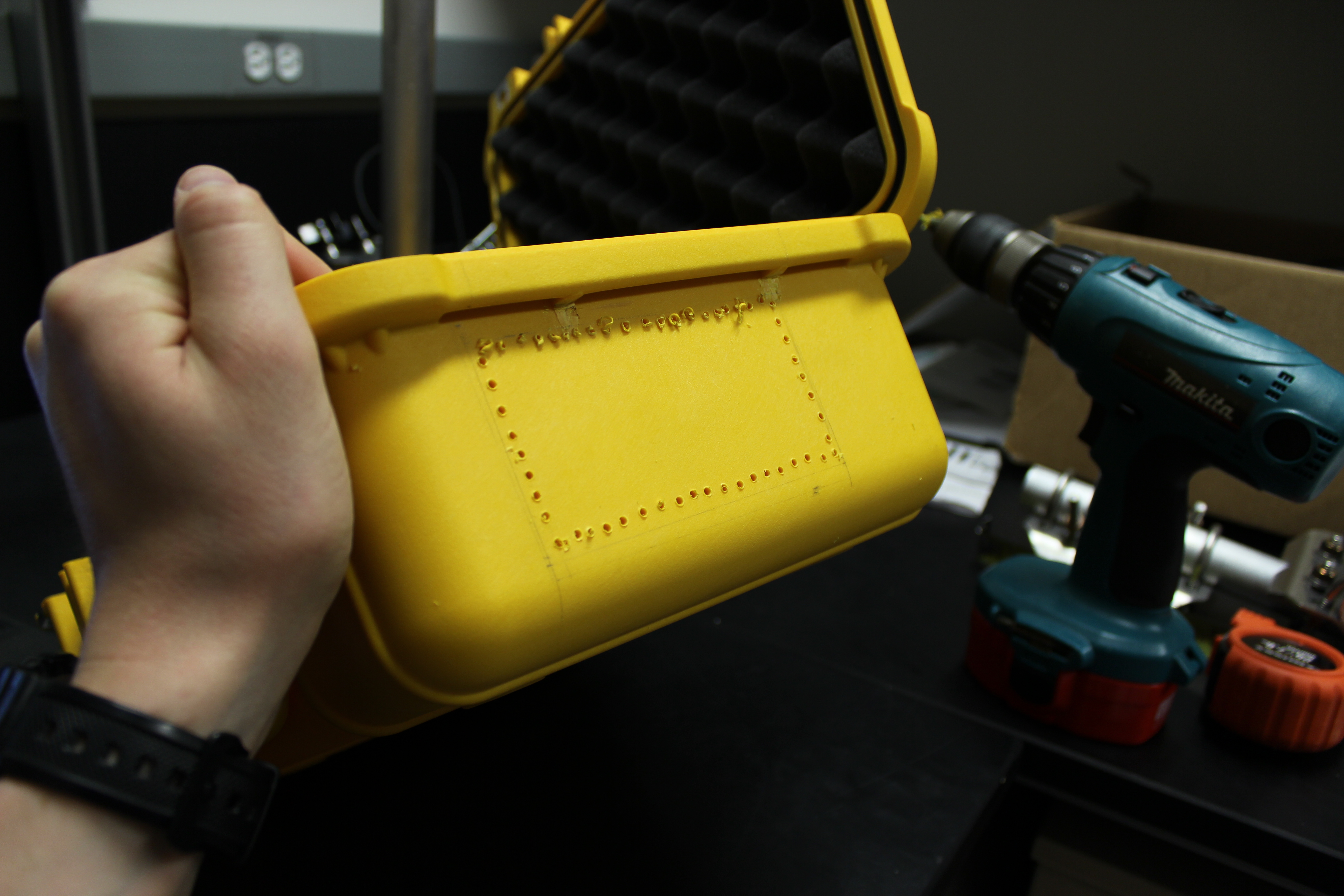
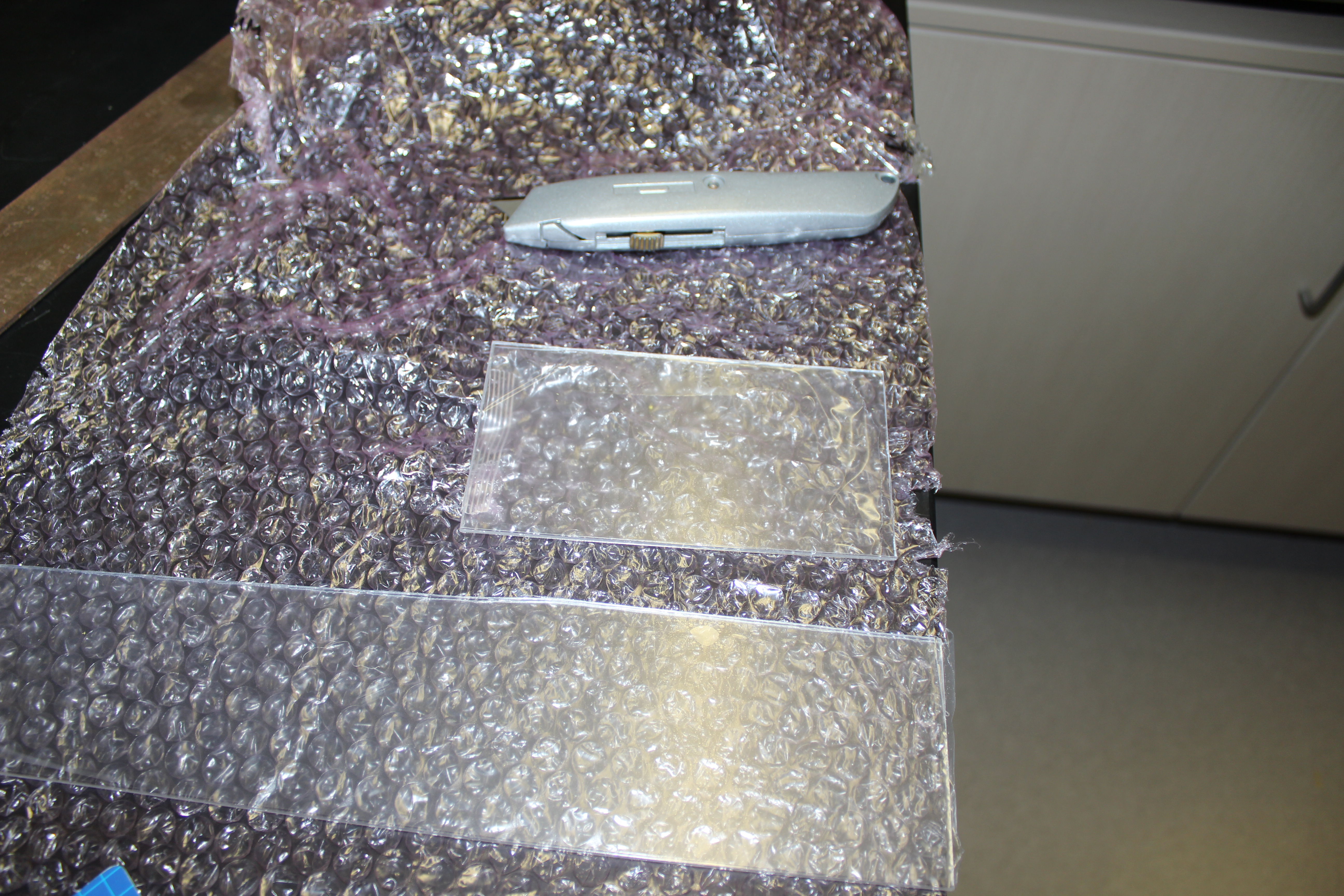
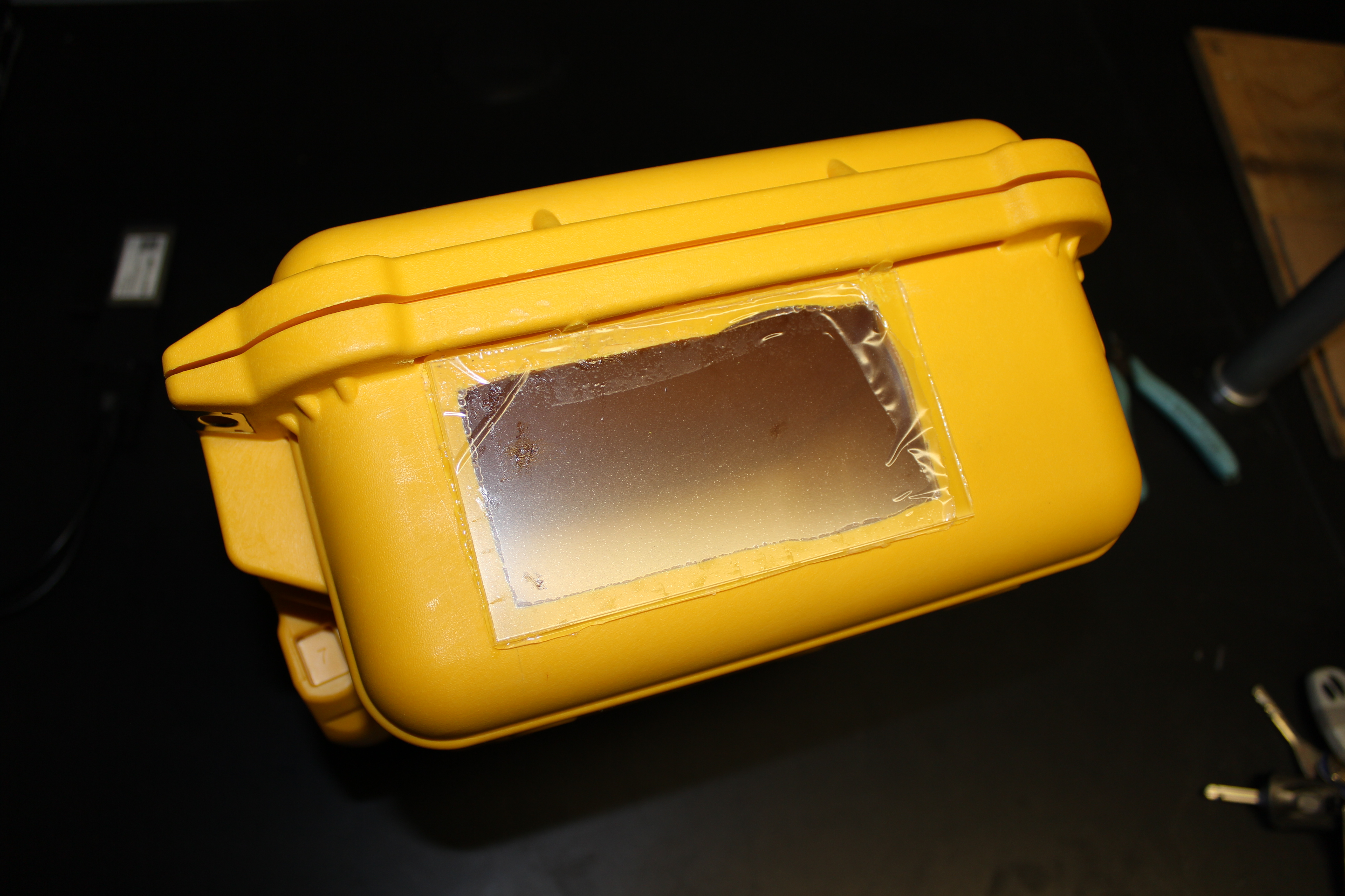
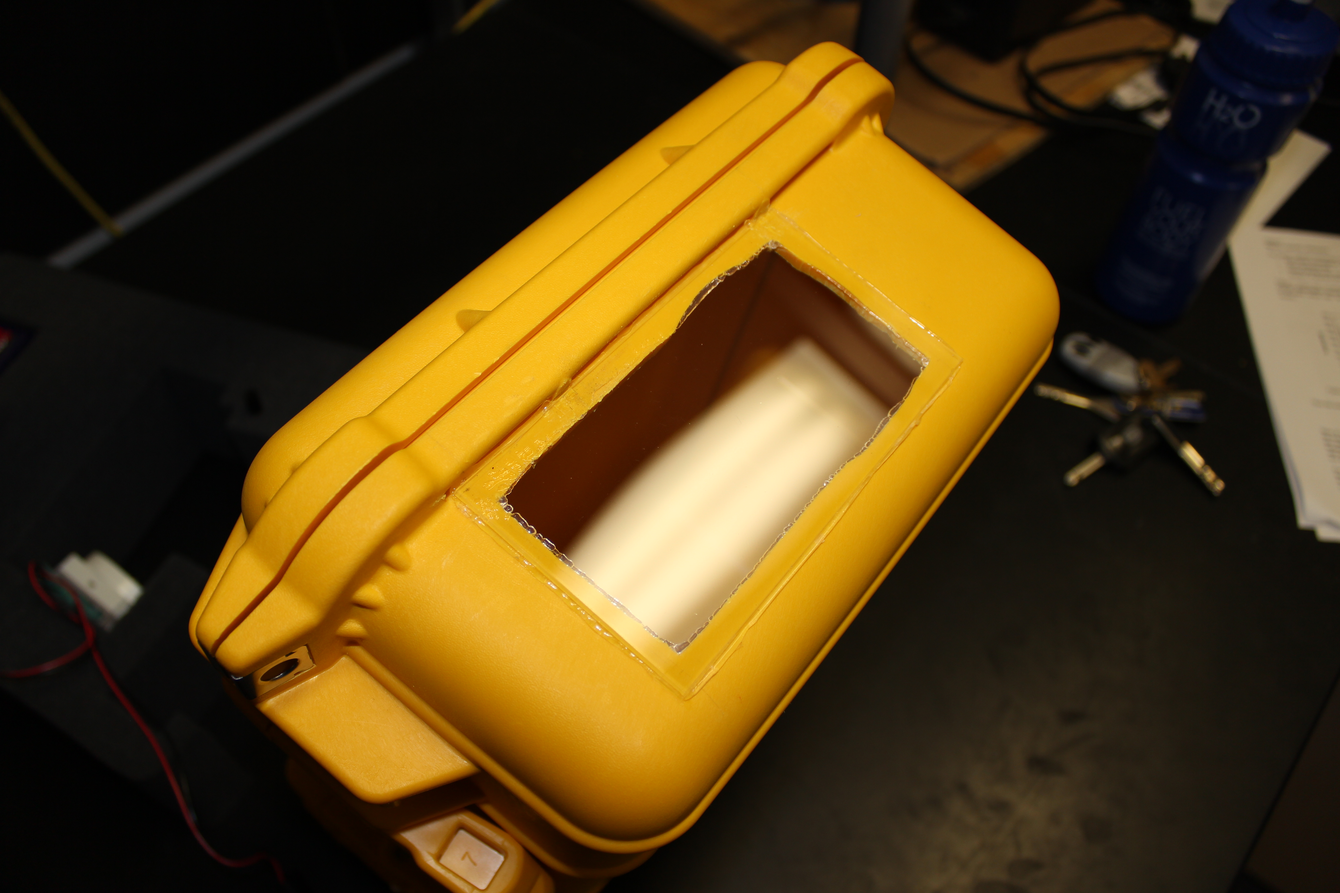
In order to weatherproof the camera rig, and keep it protected, I housed the equipment in a Pelican case. Firstly, I cut foam to fit the various components so that they are held securely in place. As a camera will not work very well in a completely opaque box, I created a window. I cut out a section of the side wall, using a drill and knife initially for the rough cut, and then a file to smooth the edges. I fitted a piece of clear acrylic for the window; I chose transparent acrylic rather than glass as it is easier to cut and is less likely to scratch or break . I bought acrylic that had a protective removable plastic covering (like cling film) which I left on until the end of building so as to avoided scratches. Basically, I treated the window like I would a lens. I used a silicone glue to attach the acrylic to the box, and left it to cure for 24 hours.


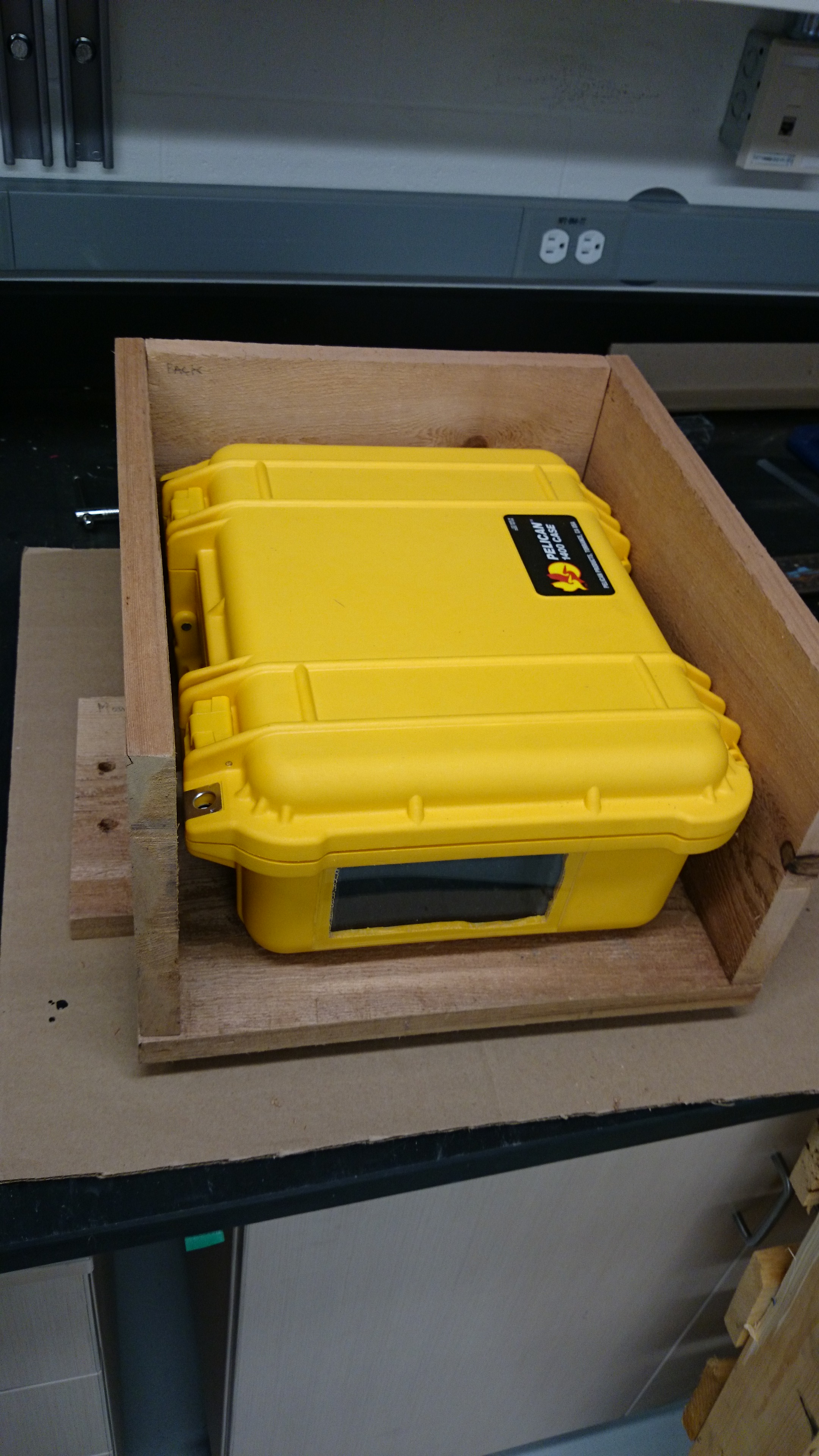
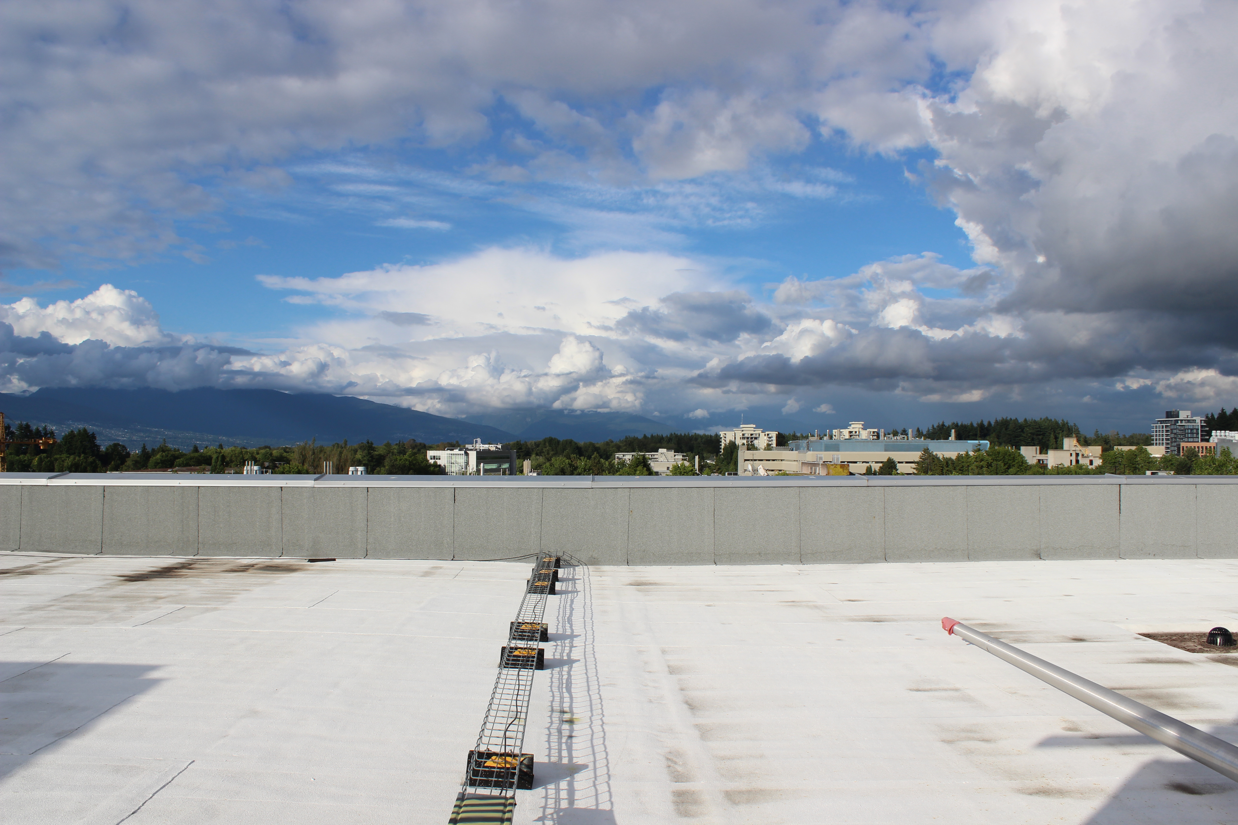
I test ran the camera on the roof of the Earth, Ocean, and Atmospheric Sciences Department here at UBC over the course of a few days, and it performed well. At the glacier, I will install the camera box in an additional wooden shelter (which I’m currently building), in order to keep it in a steady position, and to provide additional protection from anything that might damage or obscure the window. It will be set up to take images every three hours, and will hopefully provide reference and context for our data.


Update (July 4th 2014):
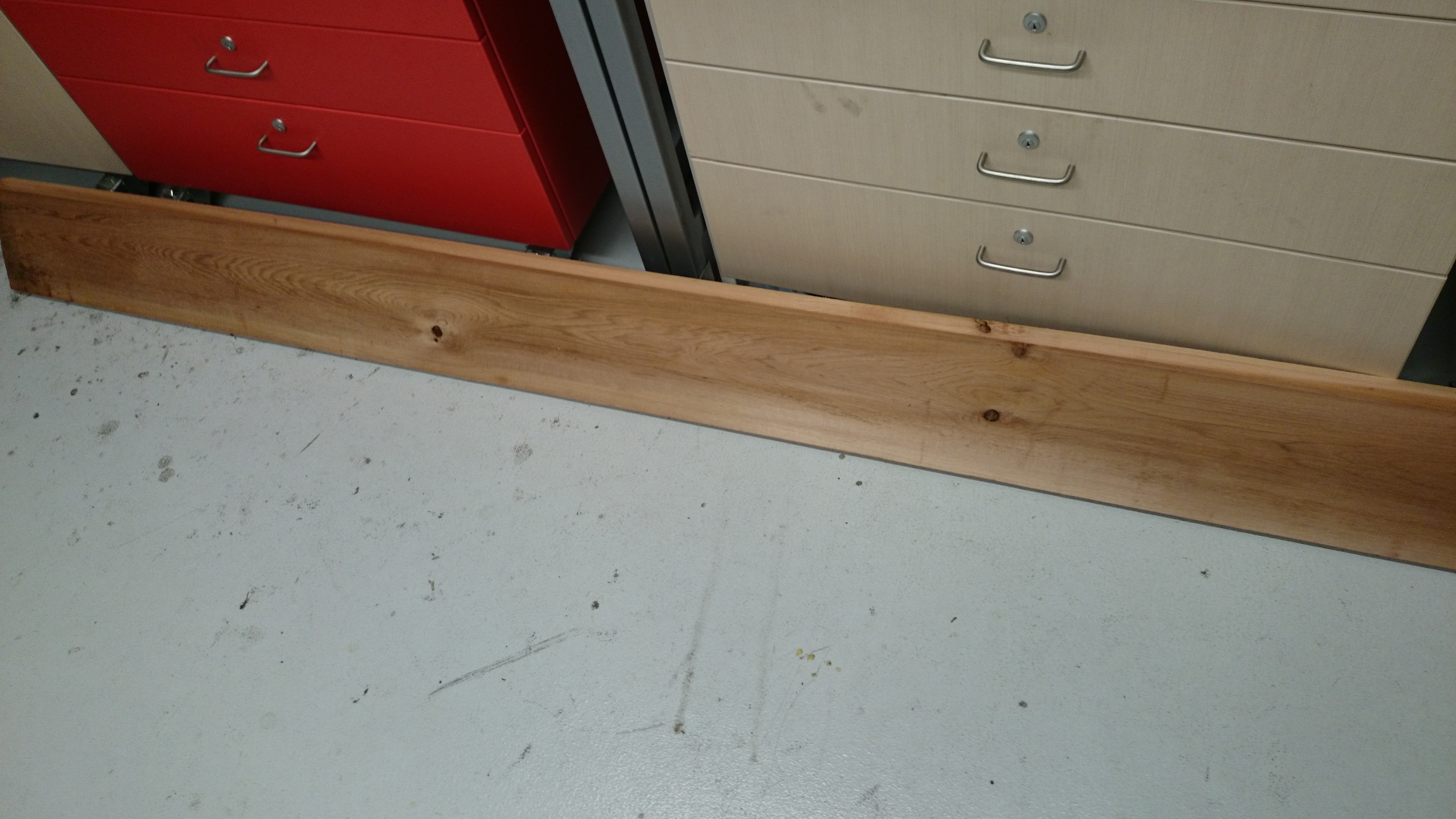
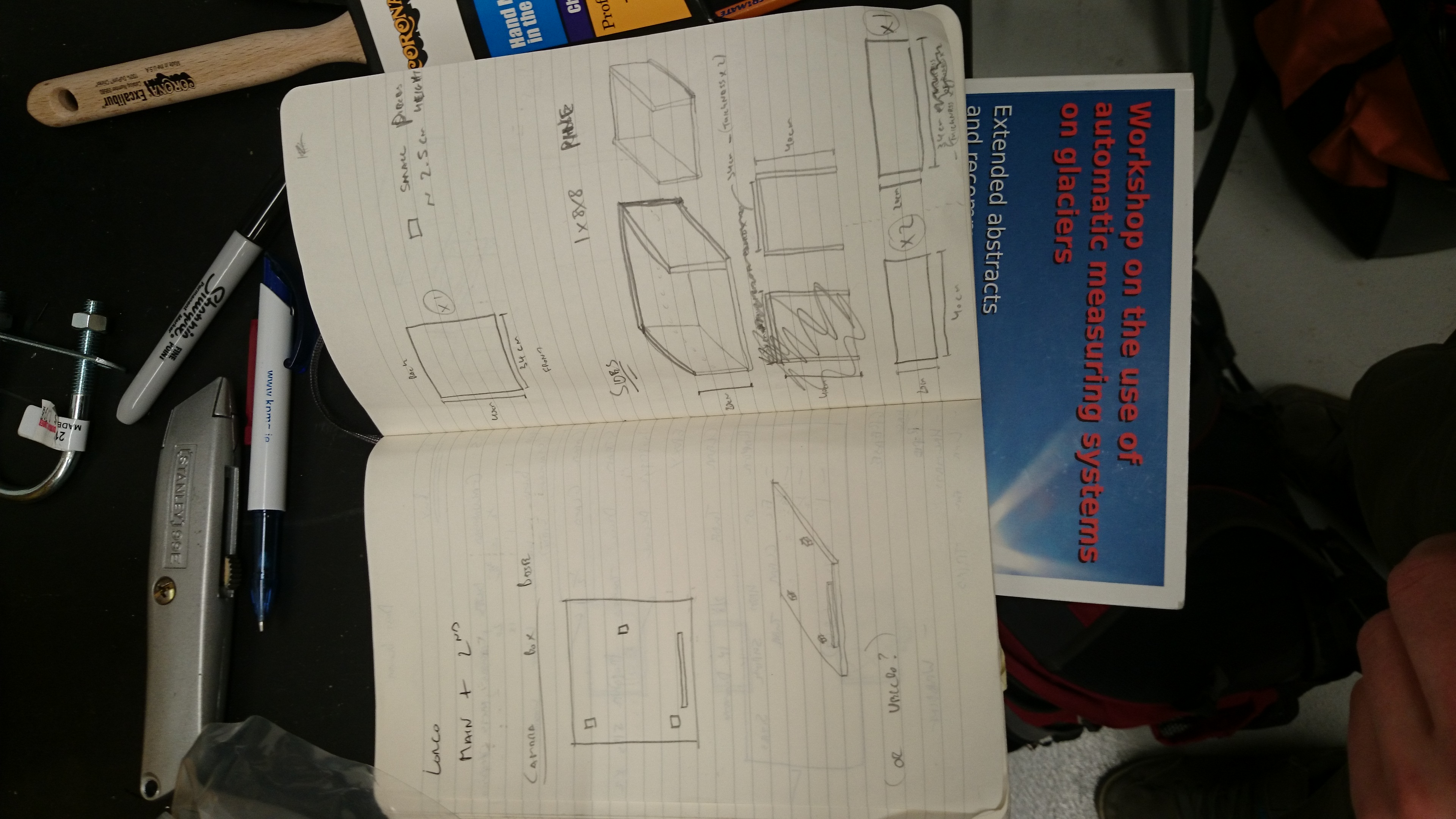
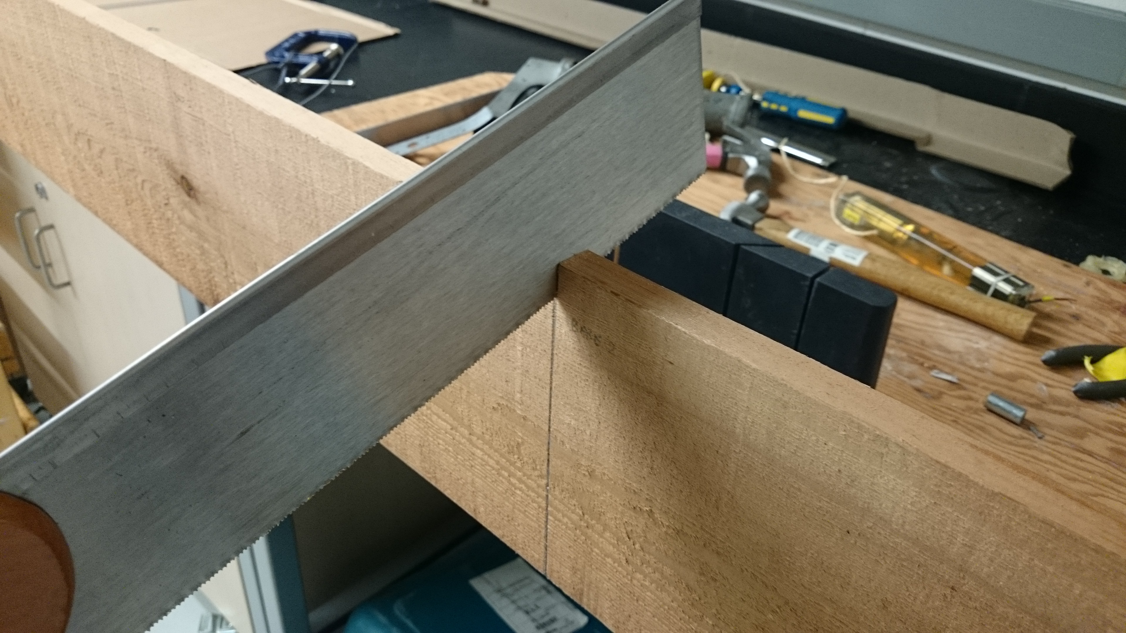
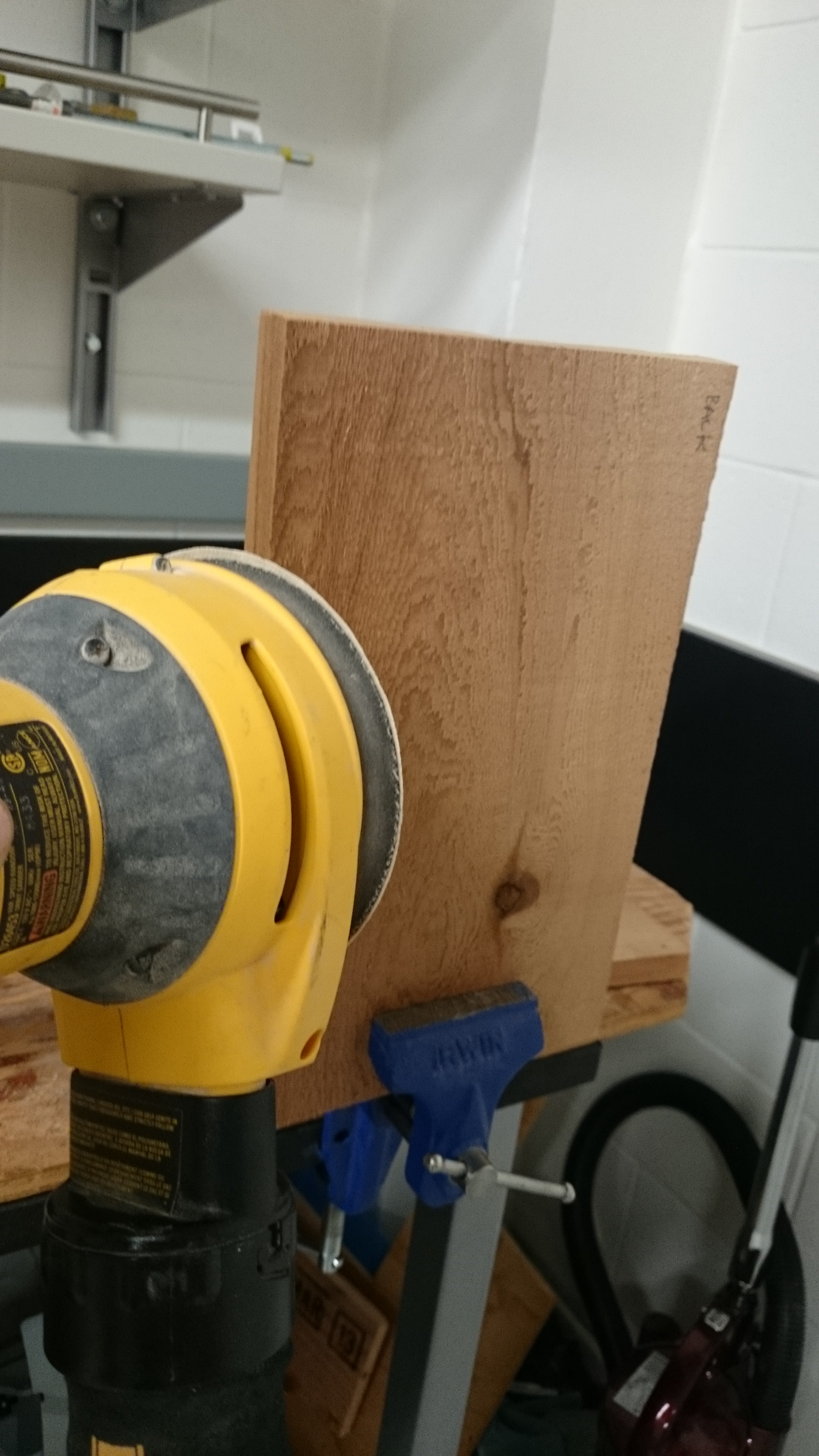
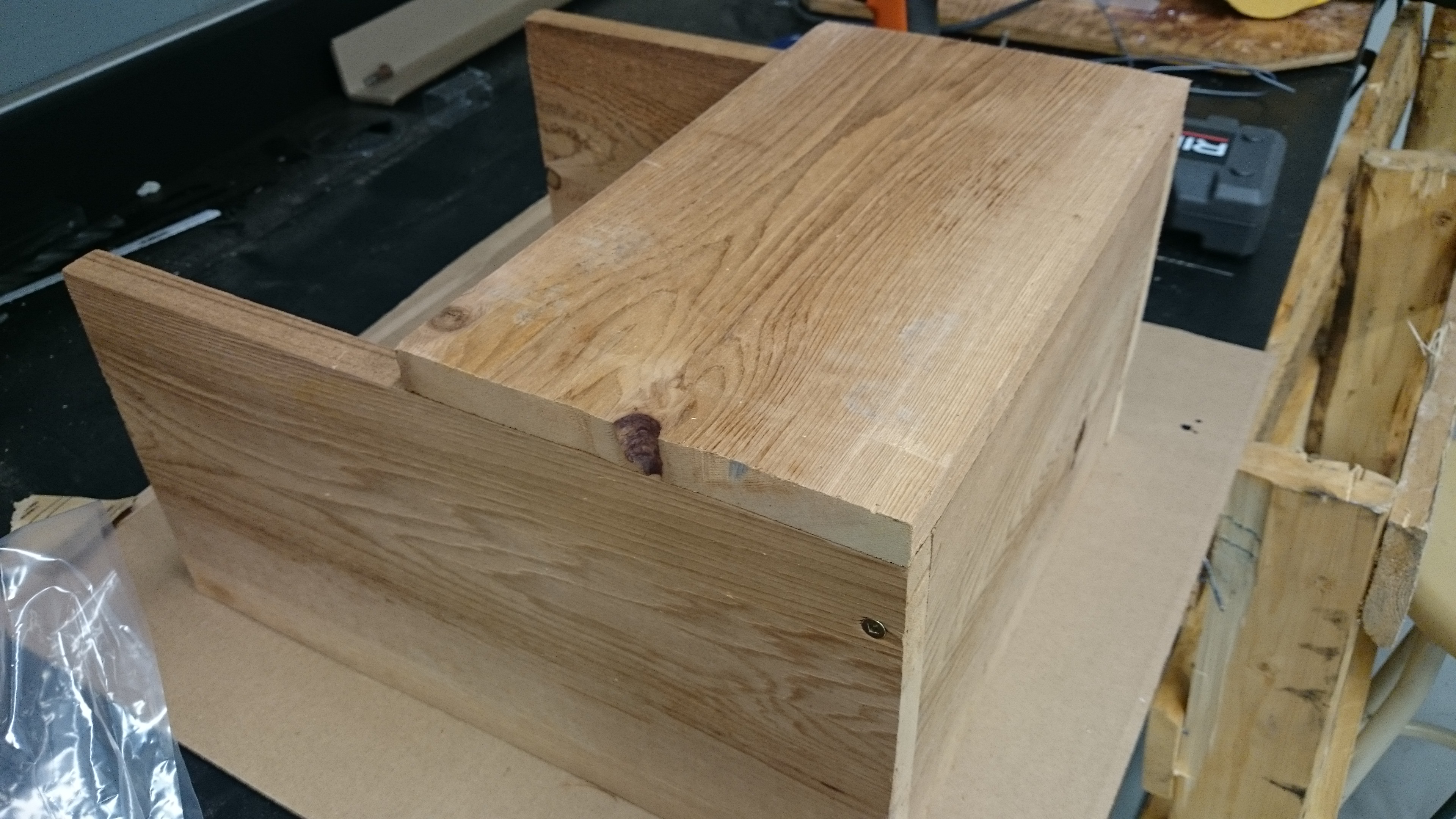
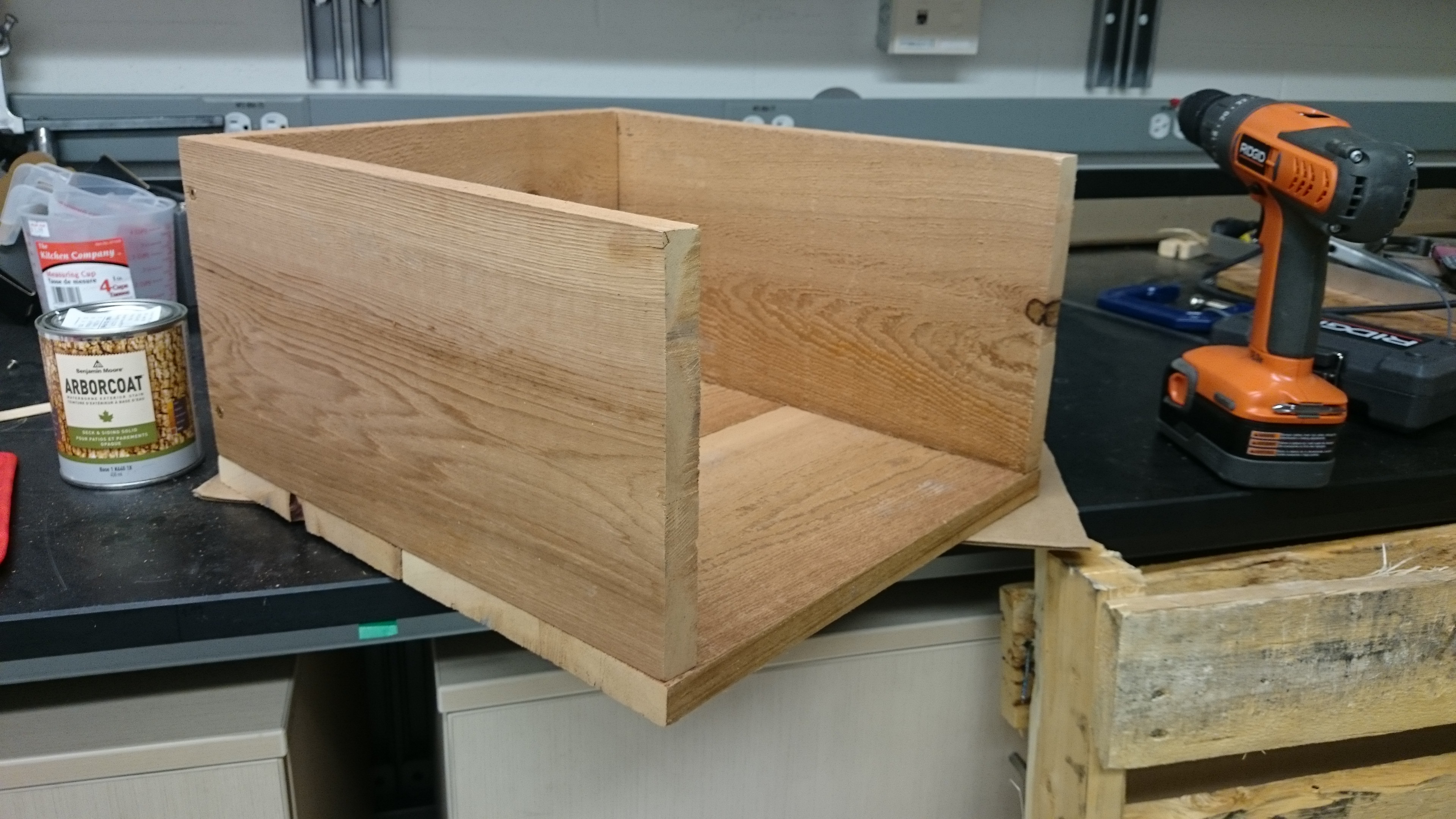
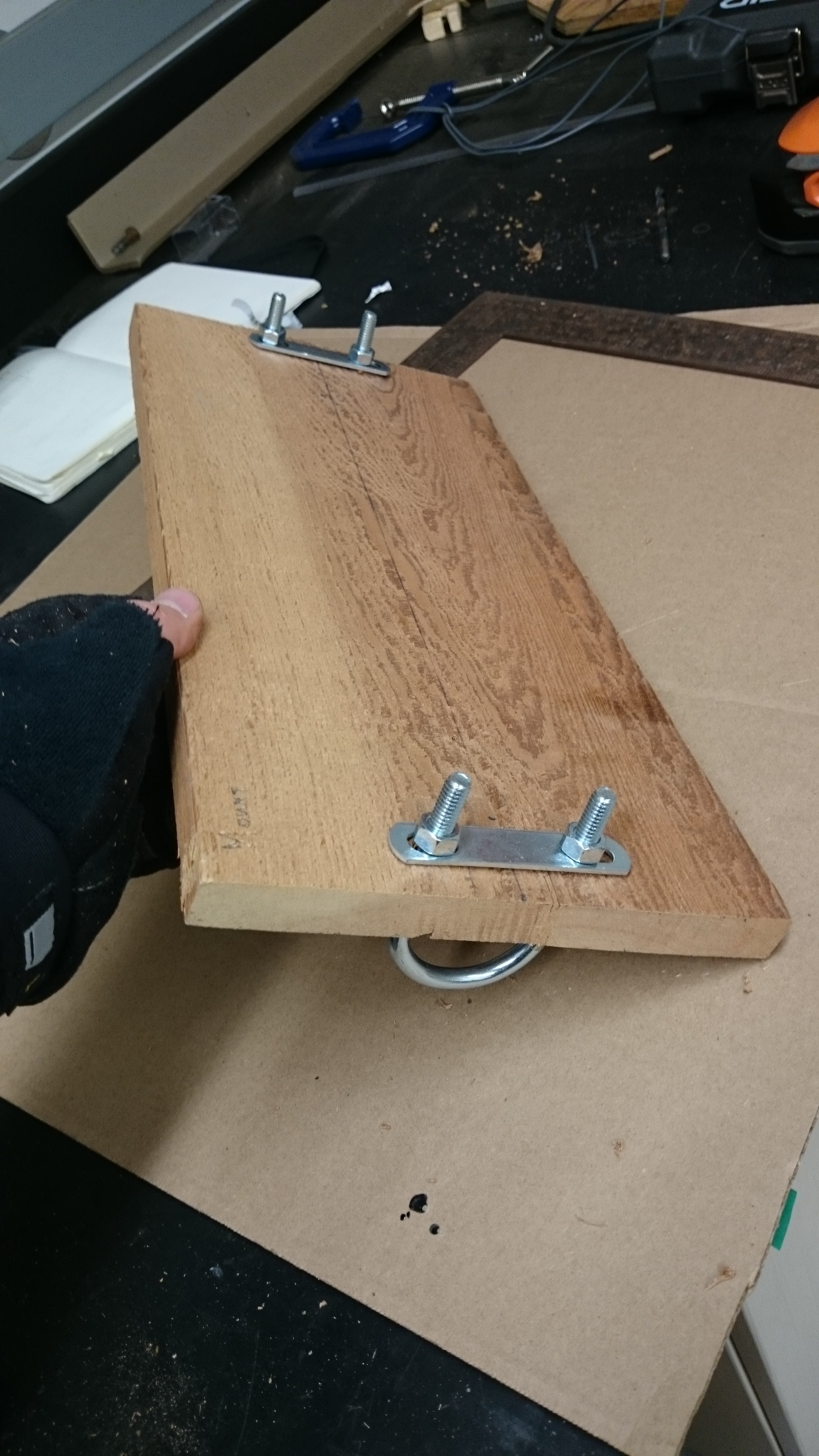
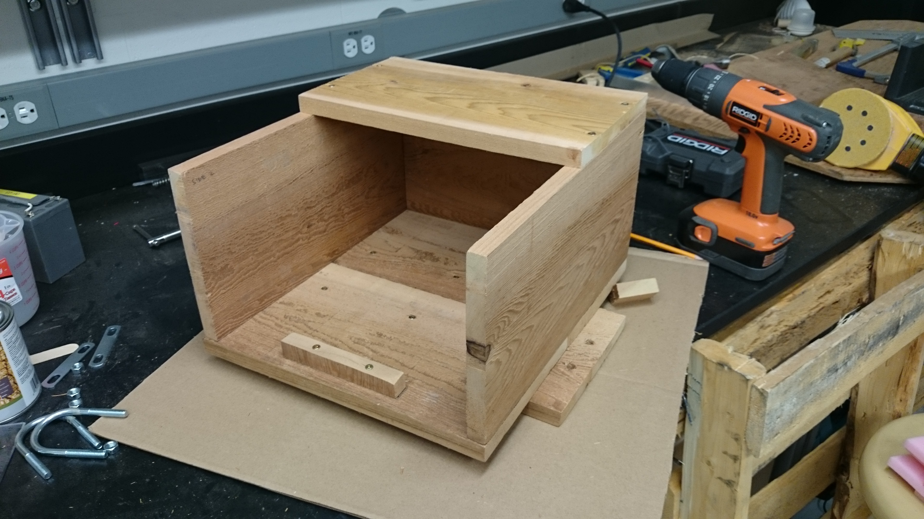
Yesterday, I built the aforementioned wooden shelter for the camera. This will act as a mount for the camera, protect the window from damage, dirt, and droplet build up, and reduce excessive heating from the sun. It was constructed using two 1″x8″x8′ pieces of cedar, some U-bolts, and assorted screws. I’m not a carpenter, and this was just a design that I thought up to solve a problem; there are probably far more elegant solutions! Below are some images from the build.