
As part of my upcoming glacier field work, it was decided that a camera would be a useful addition to the station, which will be installed and left unmanned for 2-3 months (see The Project) . The camera will be used to take pictures of the station and the surrounding site, so that I’ll have a record of what was happening throughout the study period. So, as an example, I can look at the pictures from a period with some interesting data and see what the weather was like, or as another example, what type of bear it was that destroyed my equipment.
The following is a DIY post on building a type of ‘nature’ camera. If anyone is actually interested in building something like this and requires more information, feel free to contact me.
Having priced commercially available units at round $2,500, and not being overly impressed with the camera hardware being used, I decided to build my own rig. My design was strongly influenced by that of another rig built by a researcher in my department, Camilo Rada. Here is the basic outline:
- Use a good quality DSLR camera (I’m using a Canon T3i).
- Use a high capacity battery that will supply sufficient power to the camera to operate over several months.
- Use a timer to control when power is supplied to the camera and when and how often pictures are taken.
- House everything in a weatherproof container.

The most important component of the build is the power system. I replaced the standard camera battery with a commercially available battery adapter, which is normally used to power a camera directly from a mains socket. I wired this adapter into a DC timer, which is essentially a switch which opens and closes the power circuit at user defined times. The other end of the timer was then wired to a high capacity (10 Ah) 7.4V lithium polymer battery, originally designed for use in remote controlled aircraft.


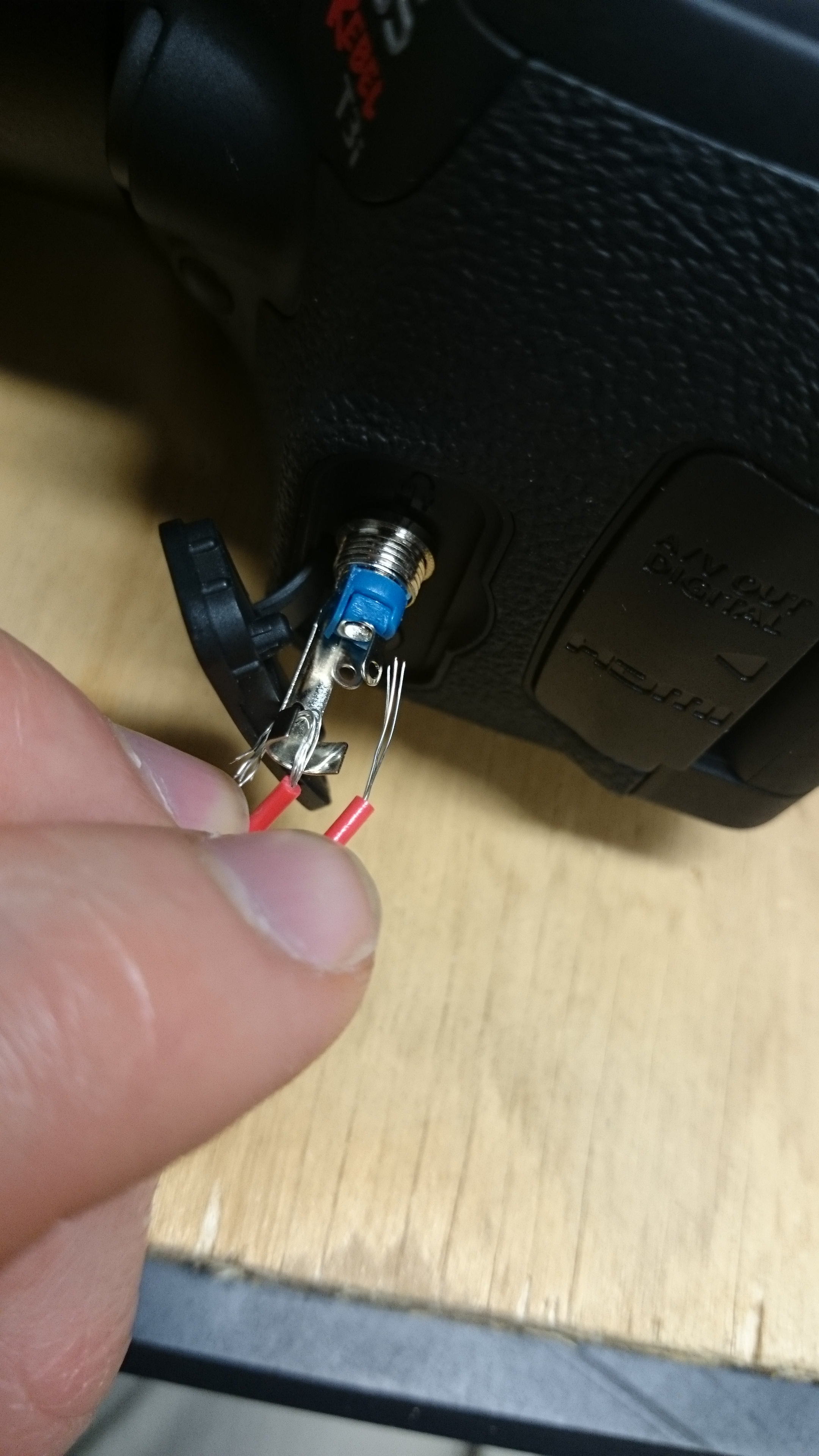
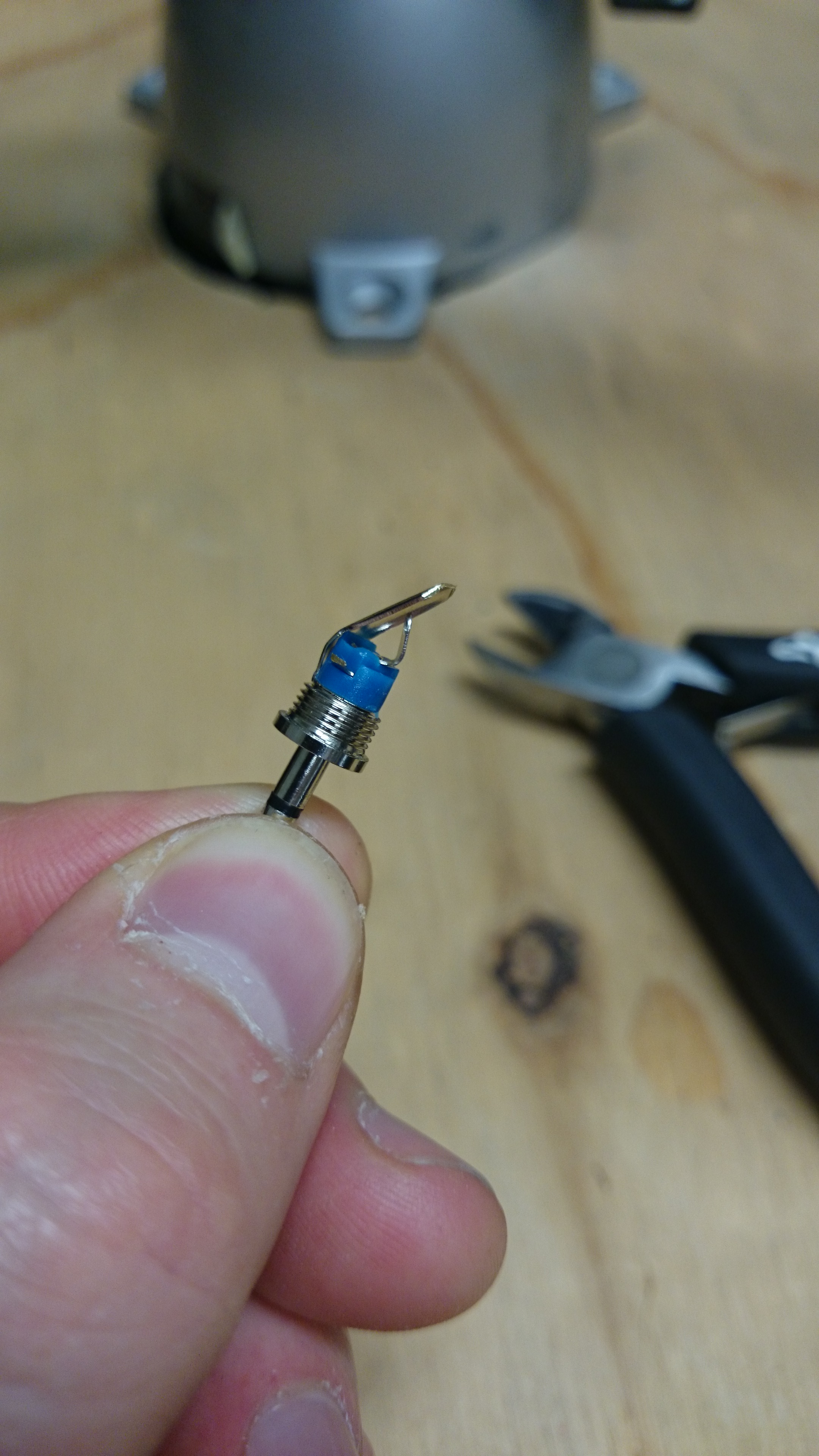
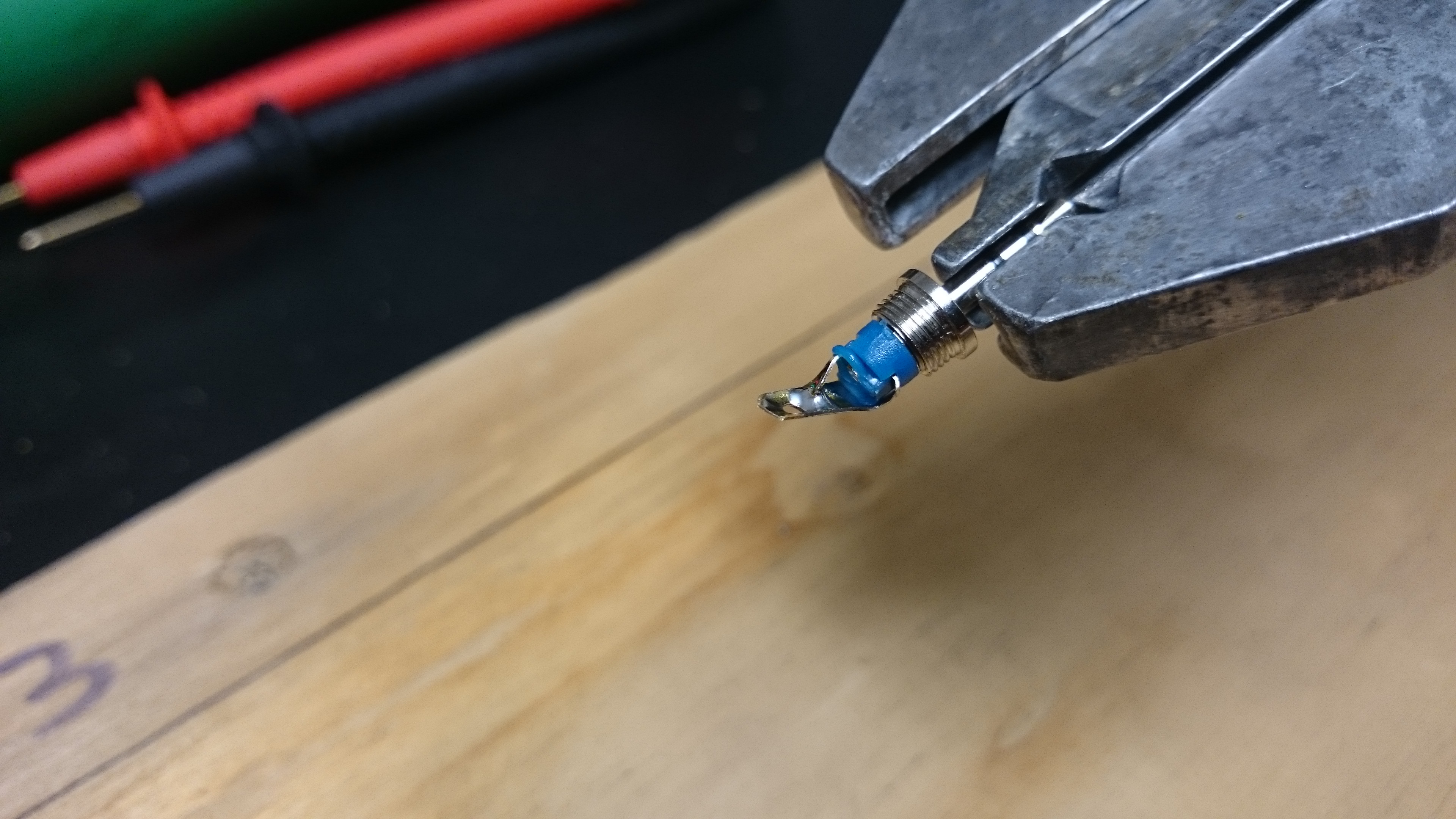
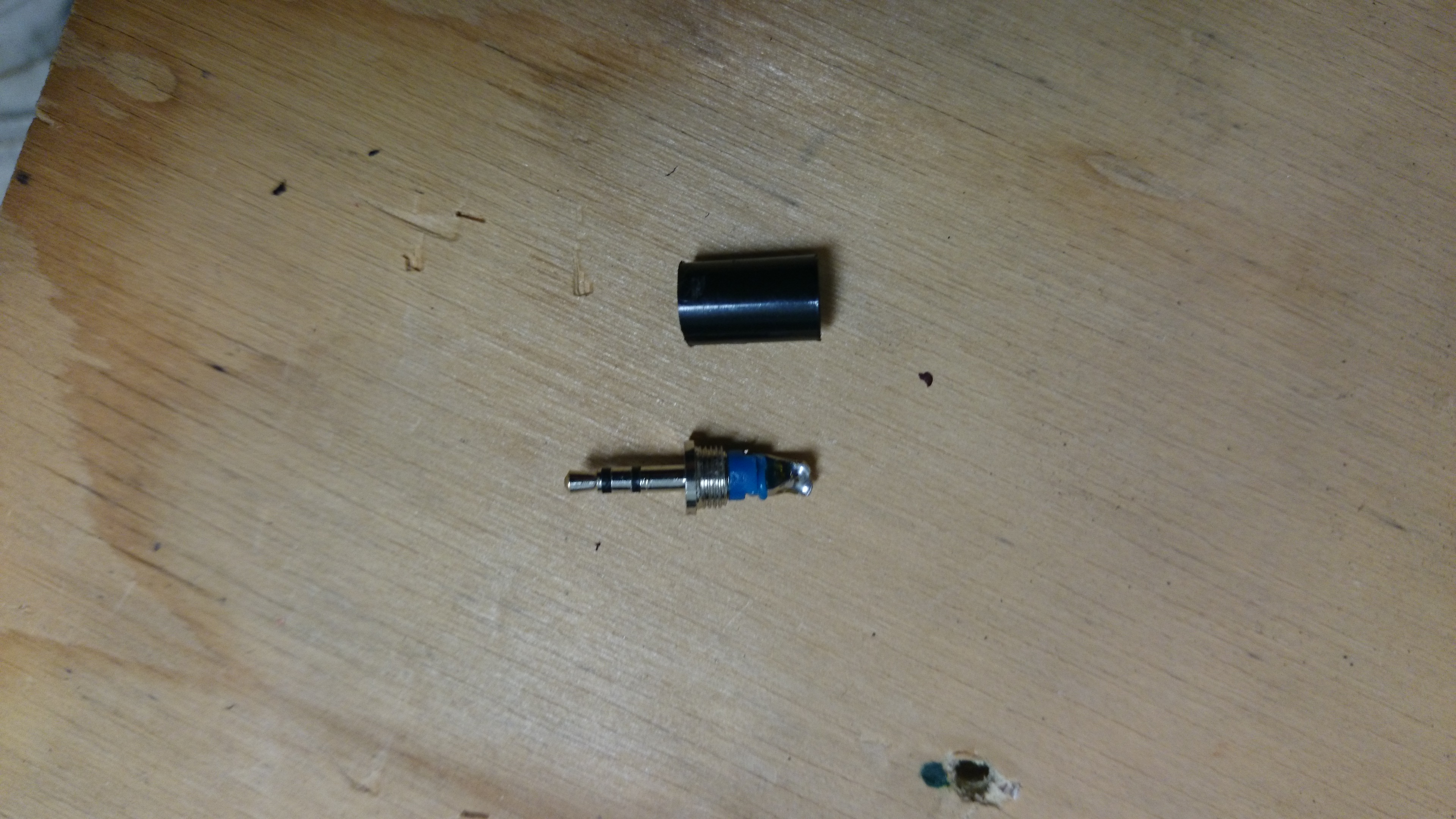
As the camera will be left to operate by itself, an automatic way of firing the shutter (taking the picture) is needed. I modified a standard 2.5mm stereo plug by shorting the outer contact (outer ring) with the inner contact (inner ring)by removing the black plastic cover and soldering the corresponding connectors together (and removing the middle connector). This plug is then inserted into the remote control port of the camera, and tells the camera that the shutter trigger is being pressed.


The timer is programmed to allow power through to the camera from the battery at set intervals, and the power switch on the camera itself is set to on. When power reaches the camera at the set times, the modified plug tells the camera that the shutter button is being pressed, and a picture is taken. After a minute, the timer shuts off power supply until the next programmed time. As for the camera settings, the mode is set to automatic (Program or P in the case of this model) so that the aperture and shutter speed will be selected automatically by the camera to suit the light conditions. The camera should be focused by the user during set up to suit the required view, and then the focus should be set to manual to prevent the camera from changing the focus during operation.


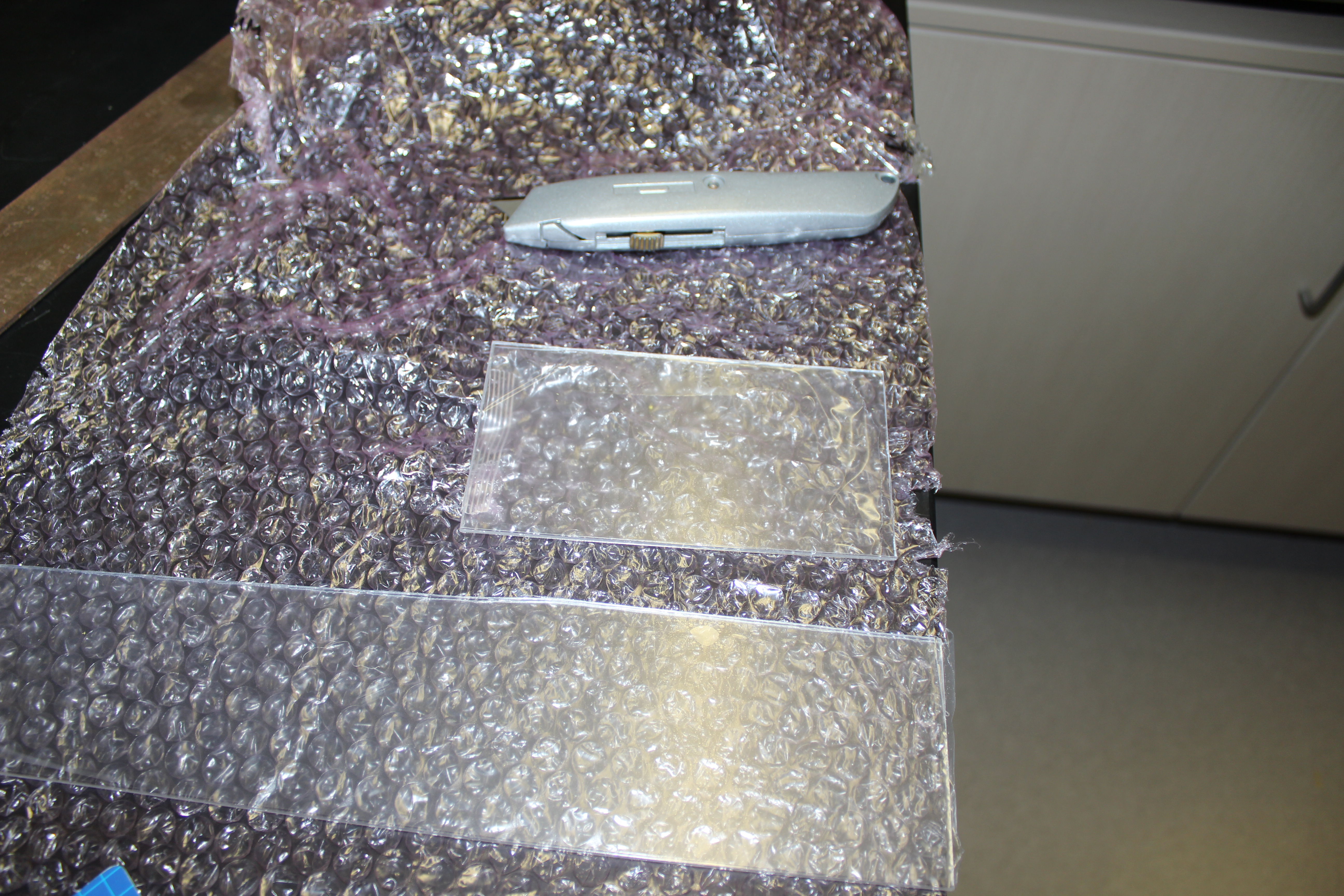
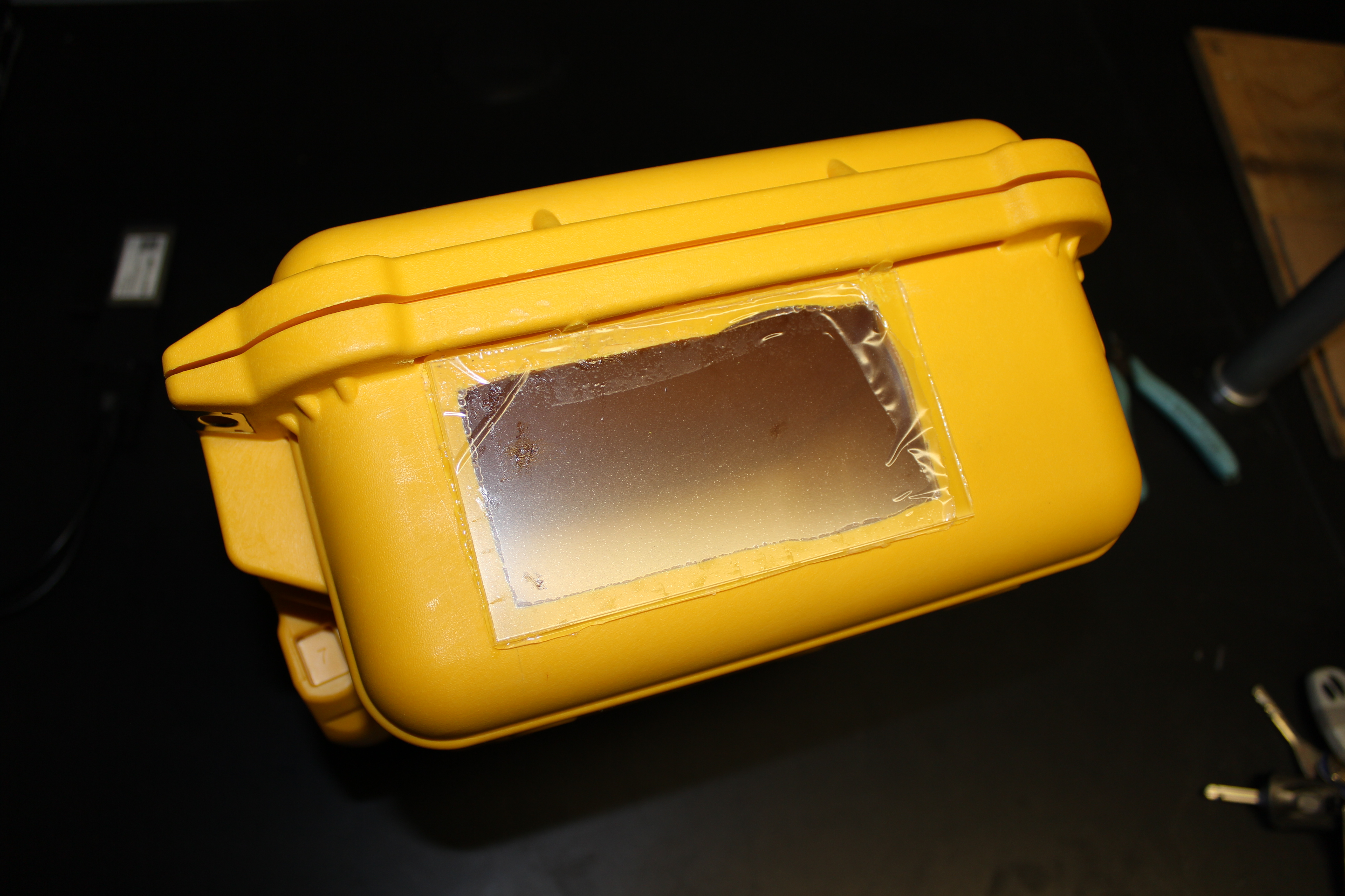
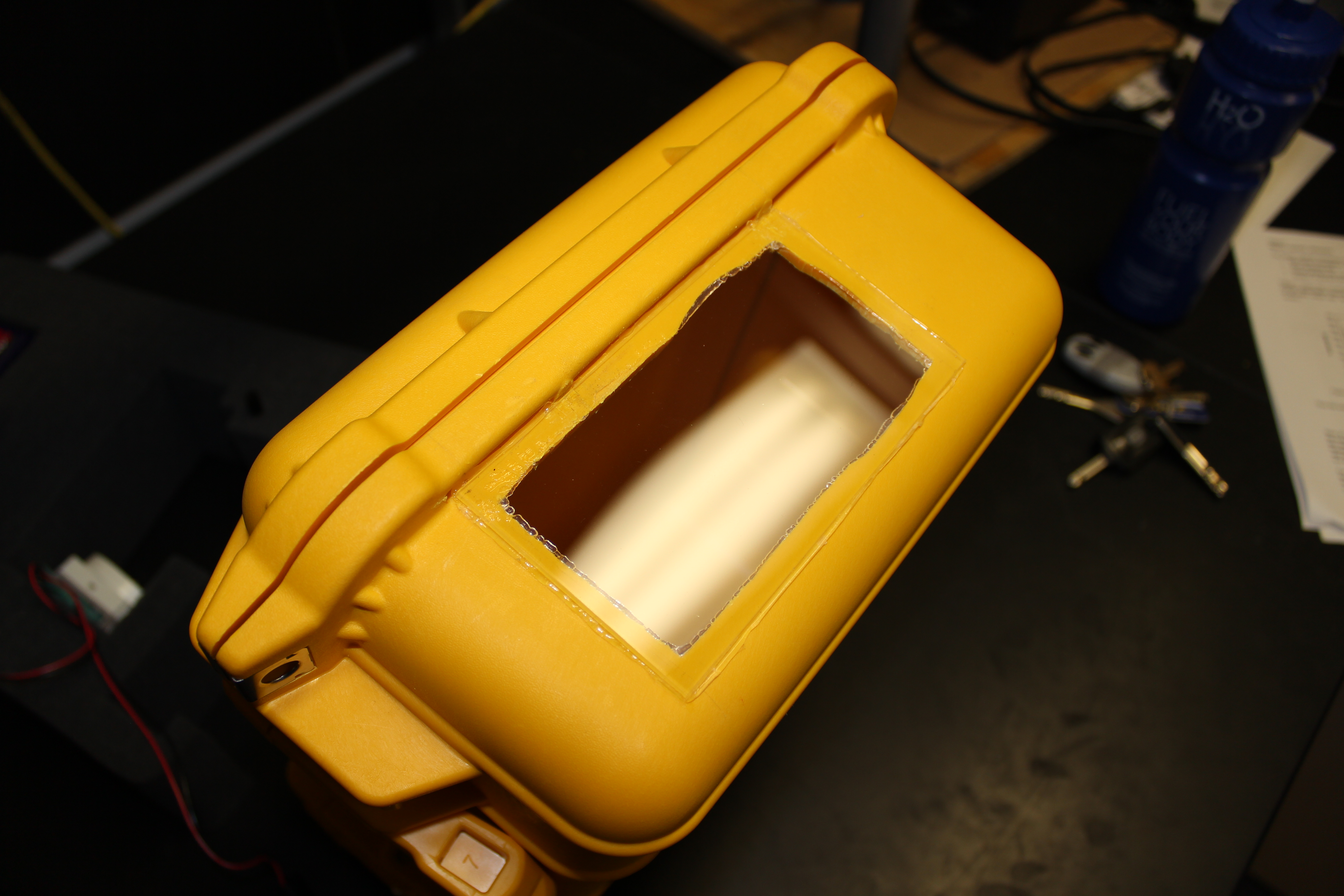
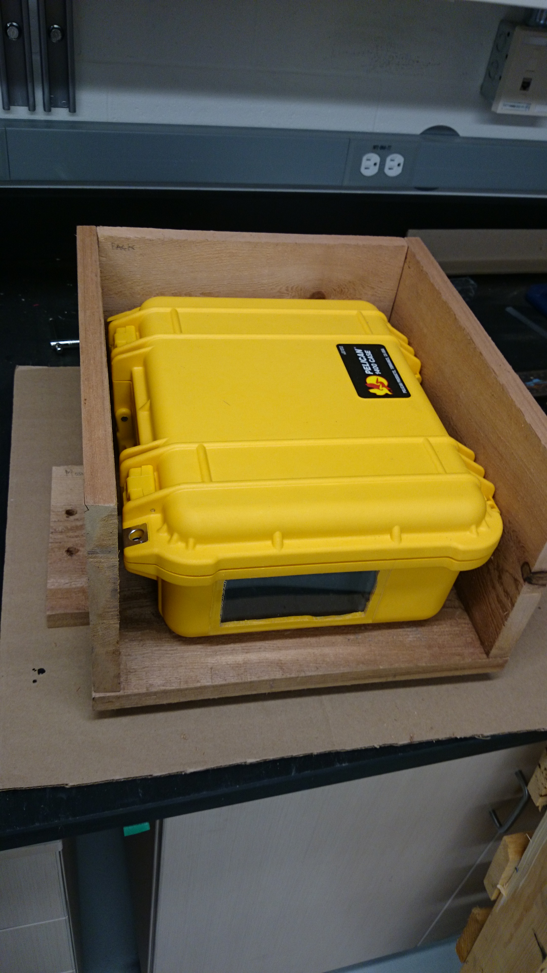
In order to weatherproof the camera rig, and keep it protected, I housed the equipment in a Pelican case. Firstly, I cut foam to fit the various components so that they are held securely in place. As a camera will not work very well in a completely opaque box, I created a window. I cut out a section of the side wall, using a drill and knife initially for the rough cut, and then a file to smooth the edges. I fitted a piece of clear acrylic for the window; I chose transparent acrylic rather than glass as it is easier to cut and is less likely to scratch or break . I bought acrylic that had a protective removable plastic covering (like cling film) which I left on until the end of building so as to avoided scratches. Basically, I treated the window like I would a lens. I used a silicone glue to attach the acrylic to the box, and left it to cure for 24 hours.


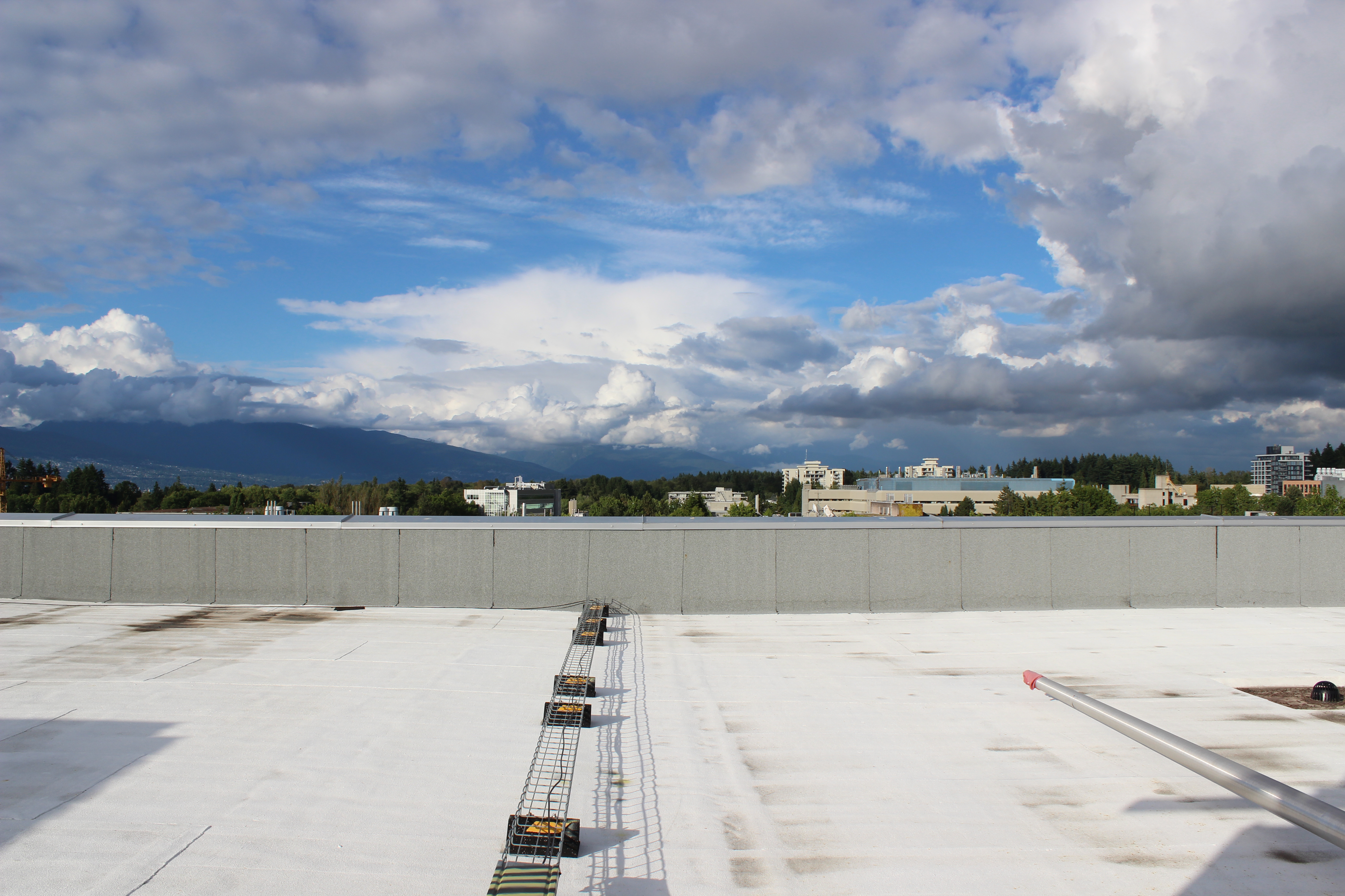
I test ran the camera on the roof of the Earth, Ocean, and Atmospheric Sciences Department here at UBC over the course of a few days, and it performed well. At the glacier, I will install the camera box in an additional wooden shelter (which I’m currently building), in order to keep it in a steady position, and to provide additional protection from anything that might damage or obscure the window. It will be set up to take images every three hours, and will hopefully provide reference and context for our data.


Update (July 4th 2014):
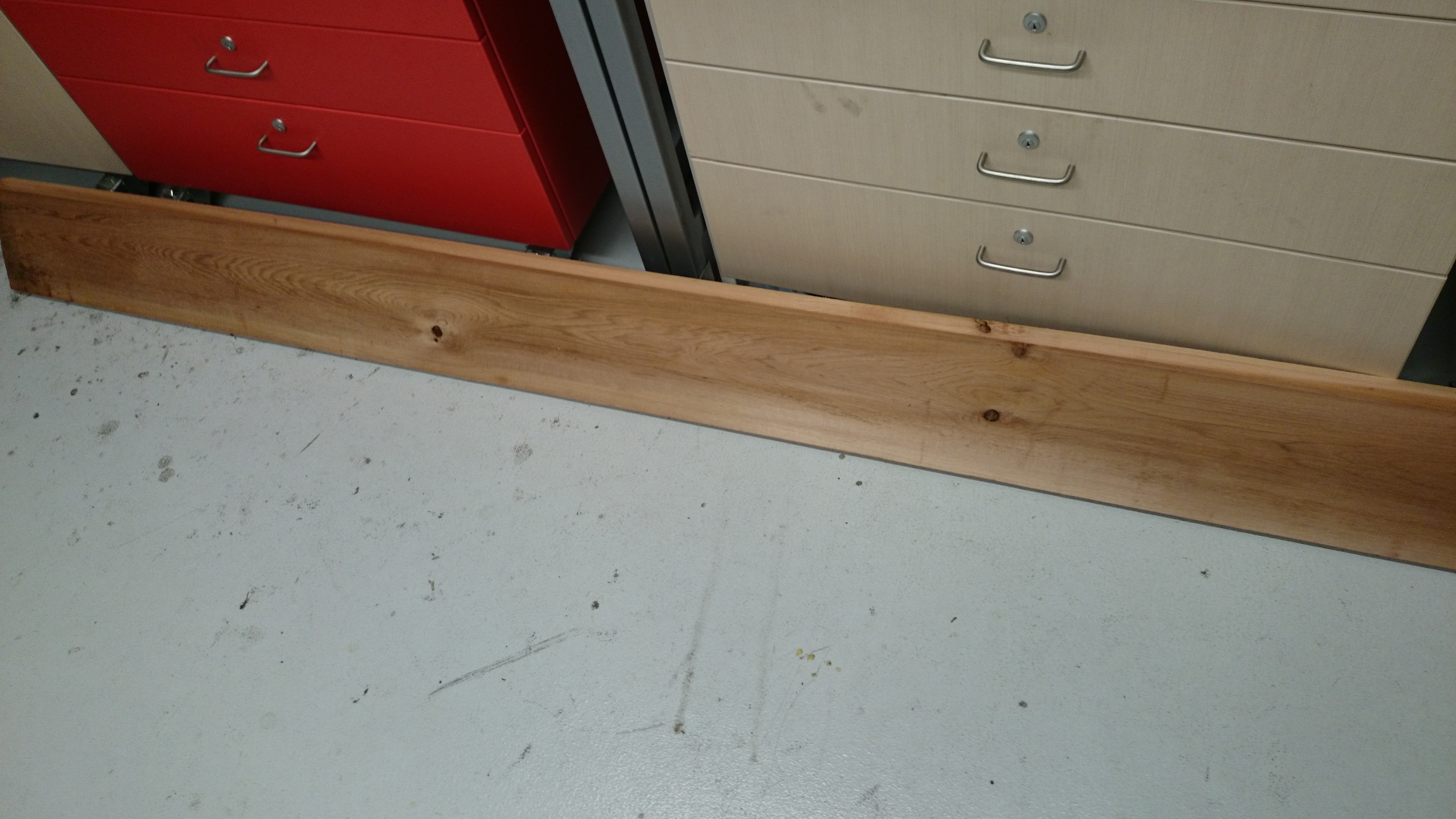
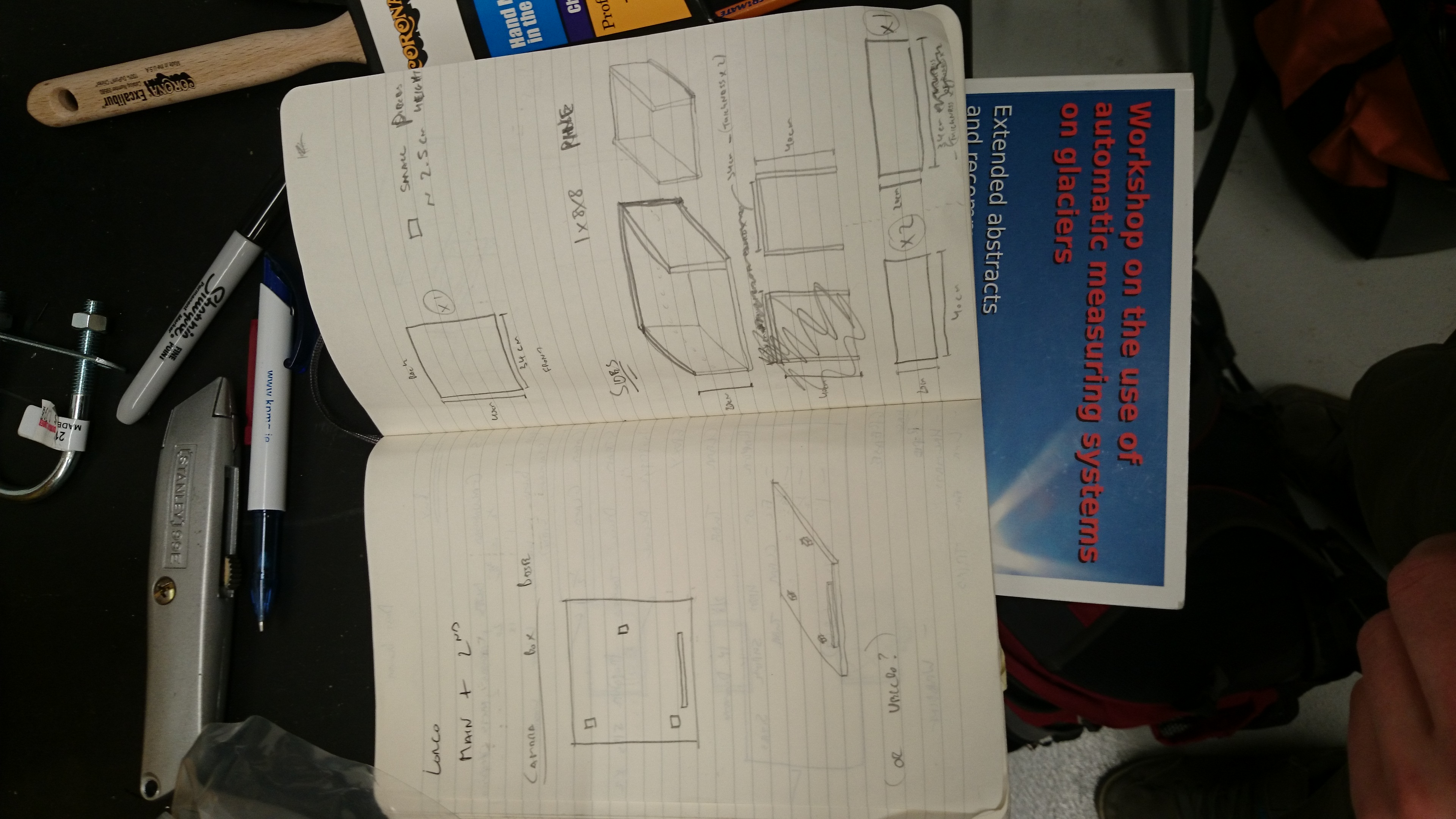
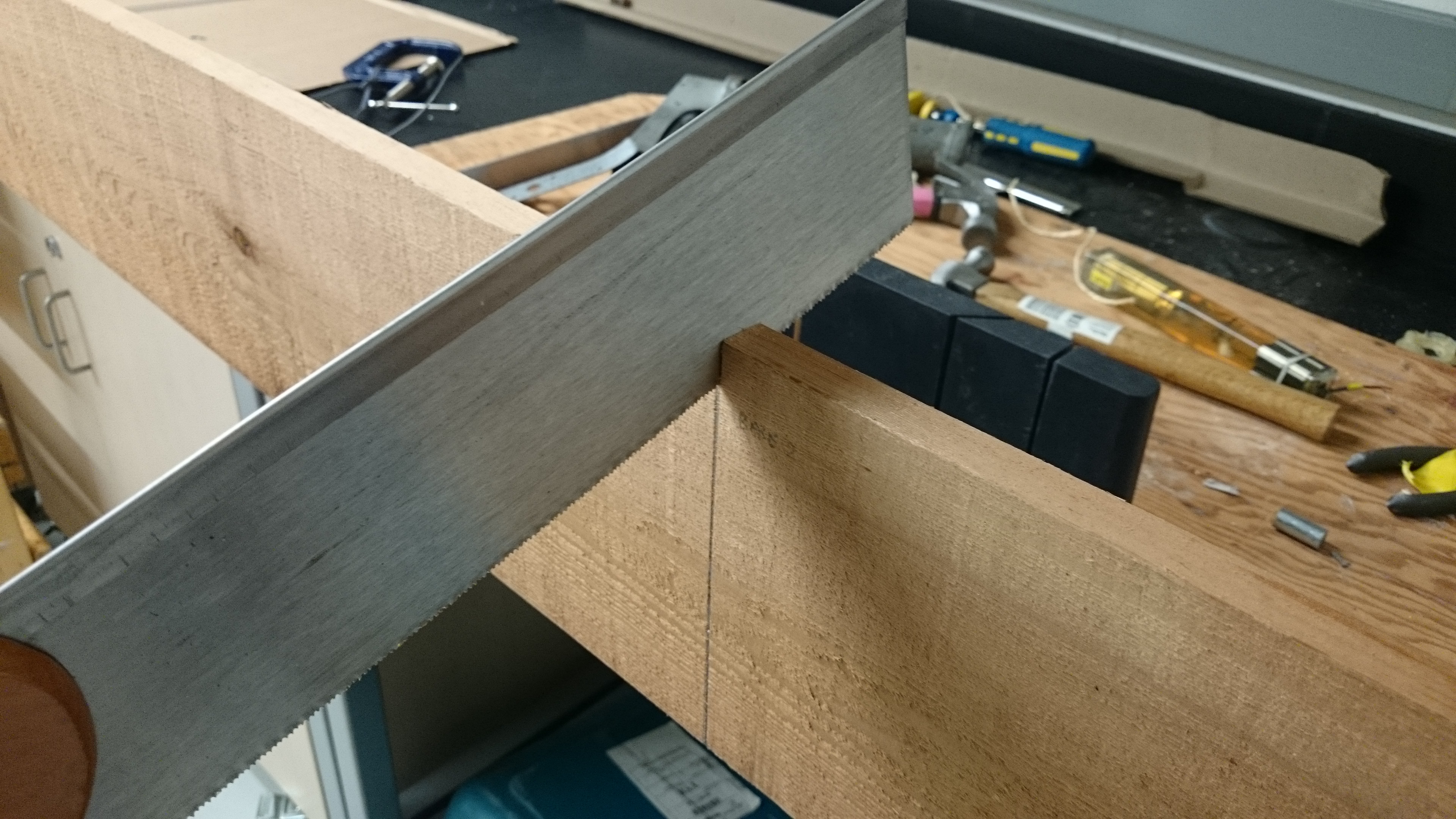
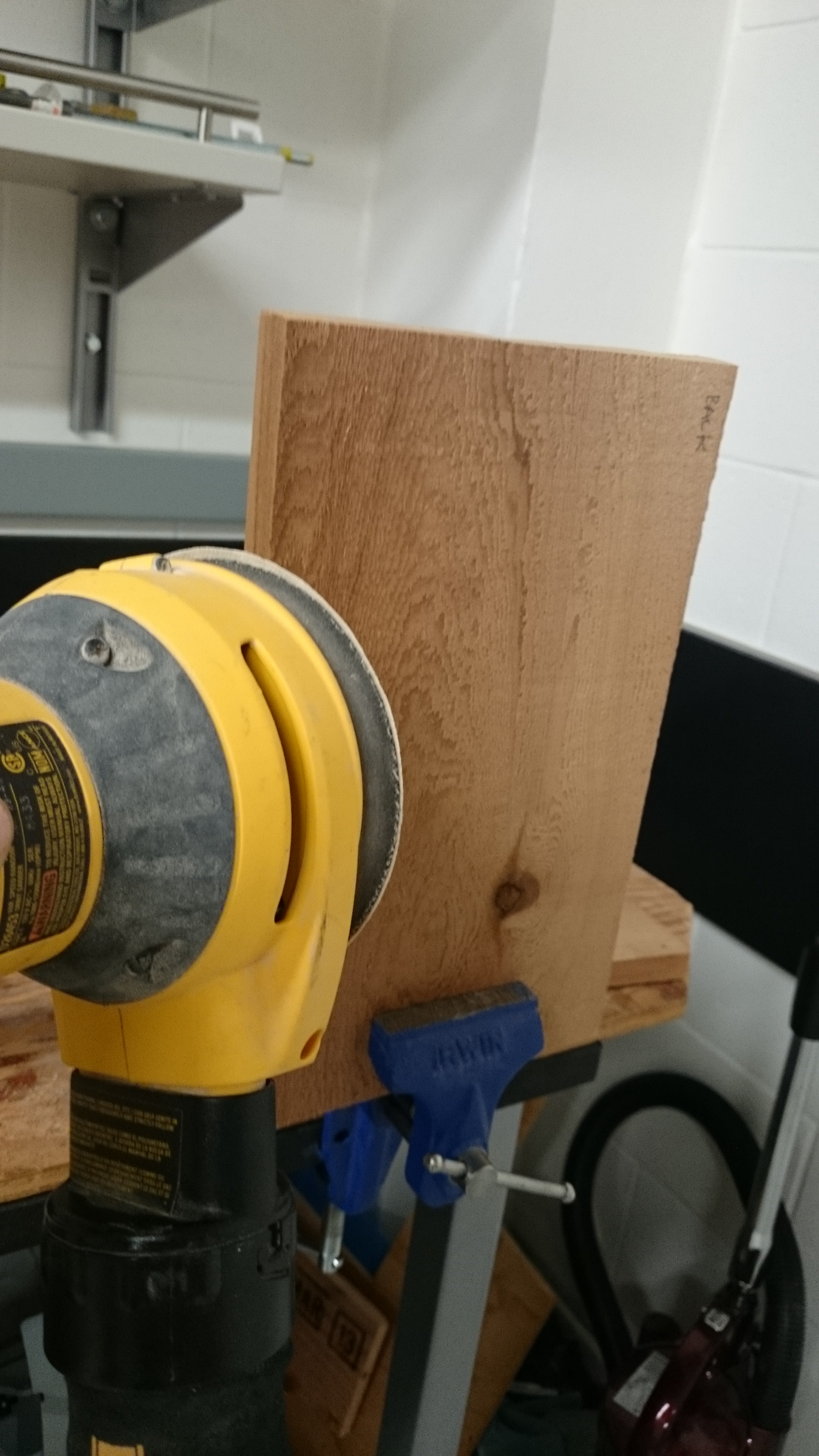
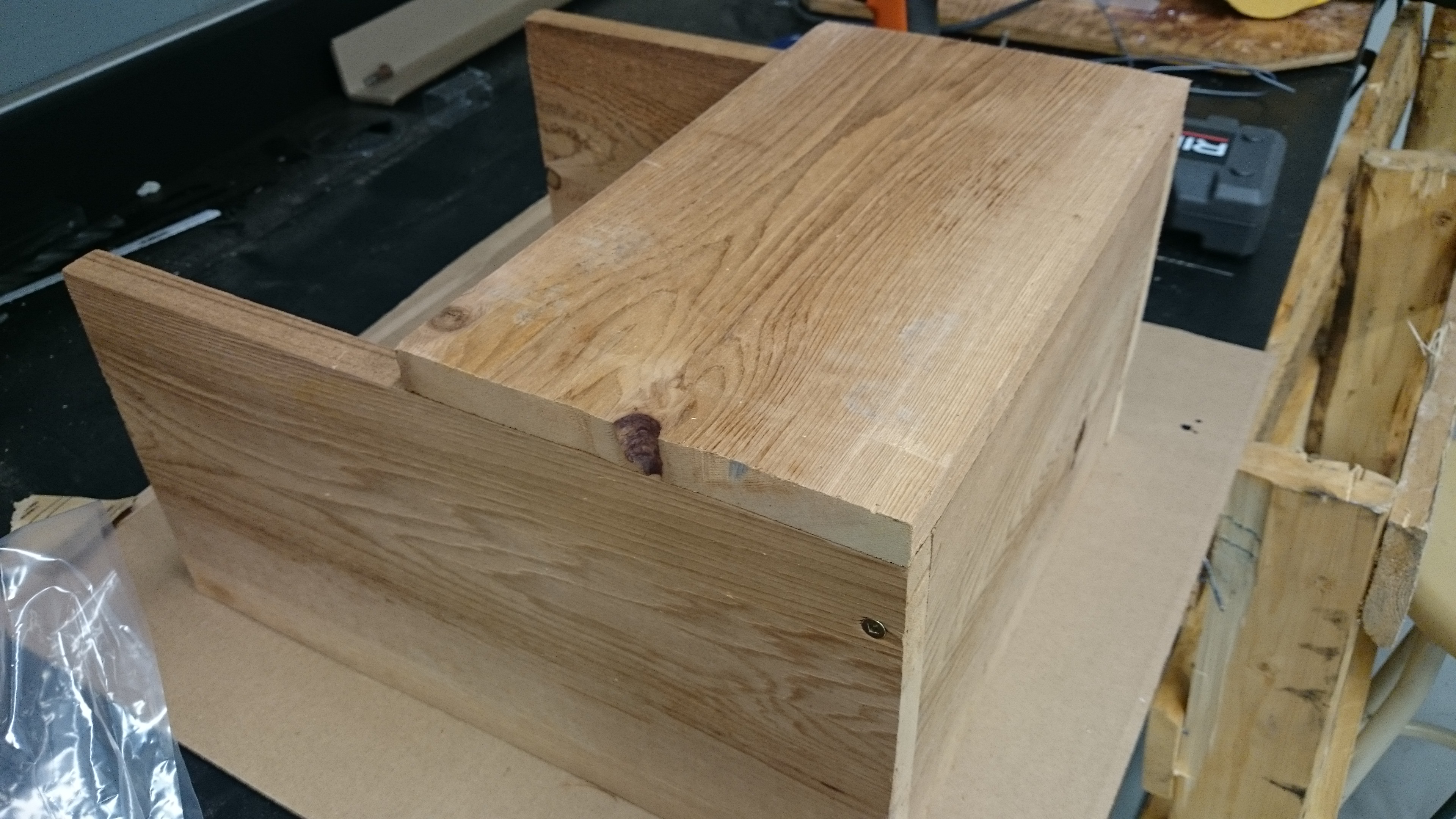
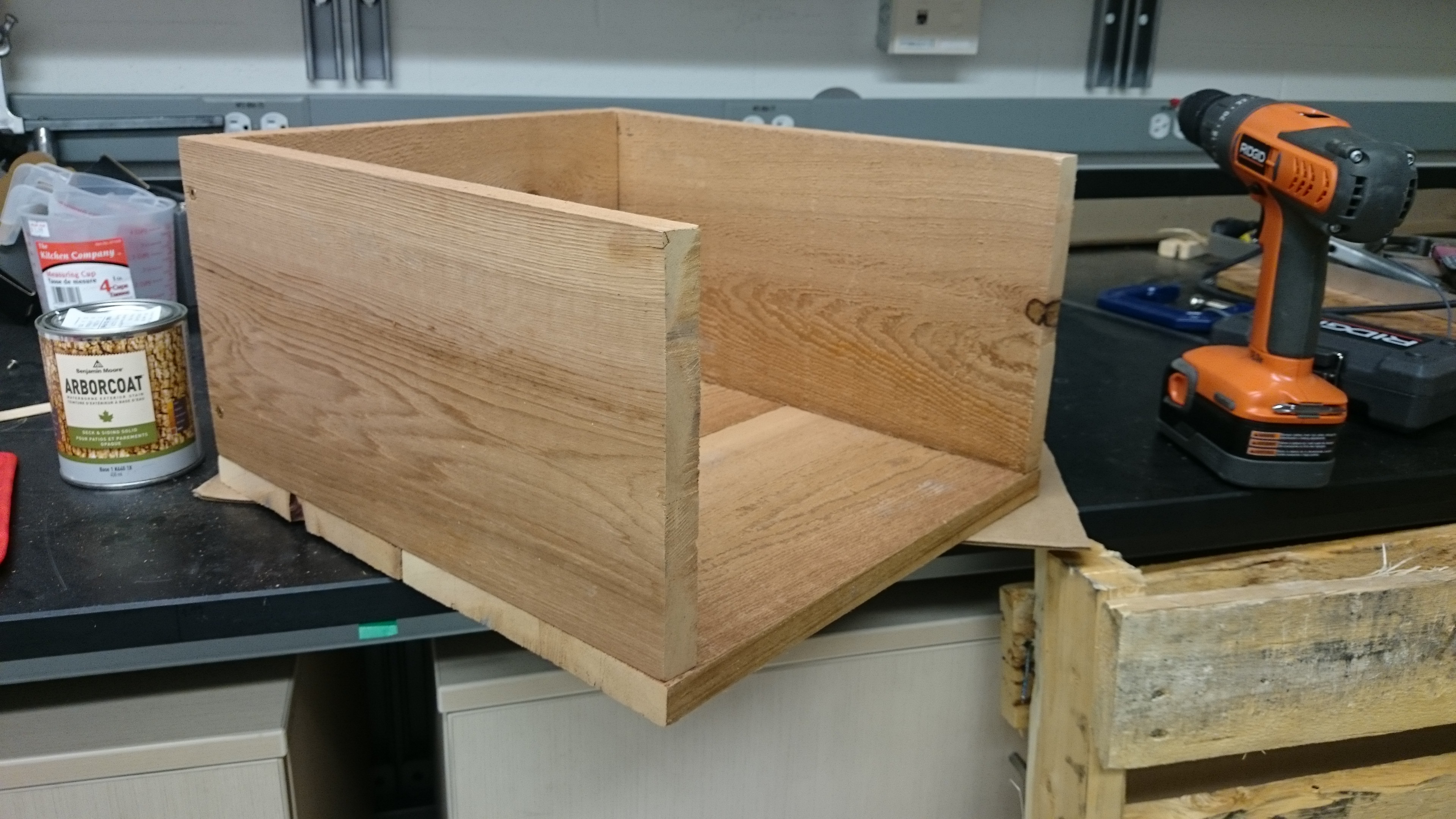
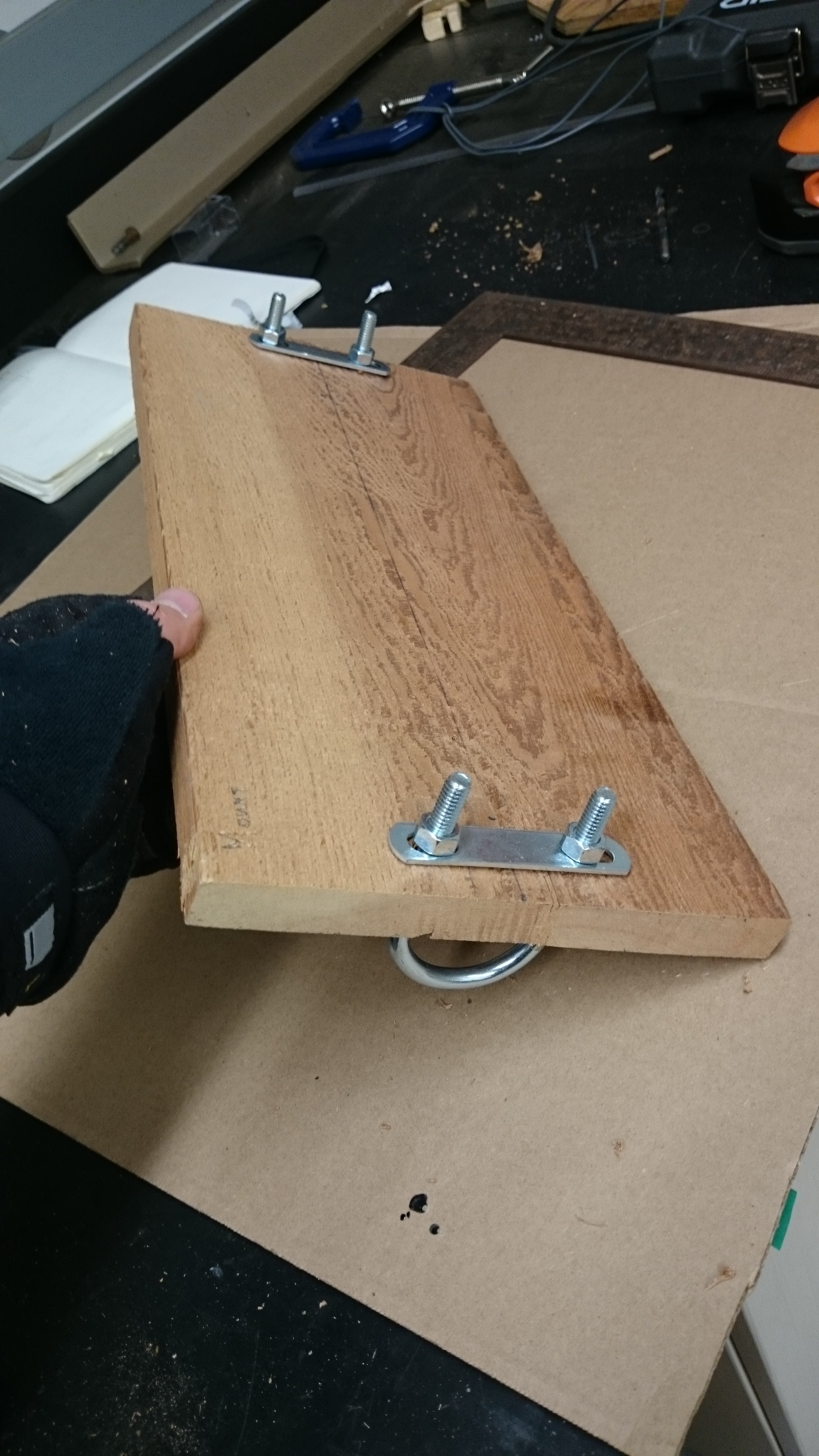
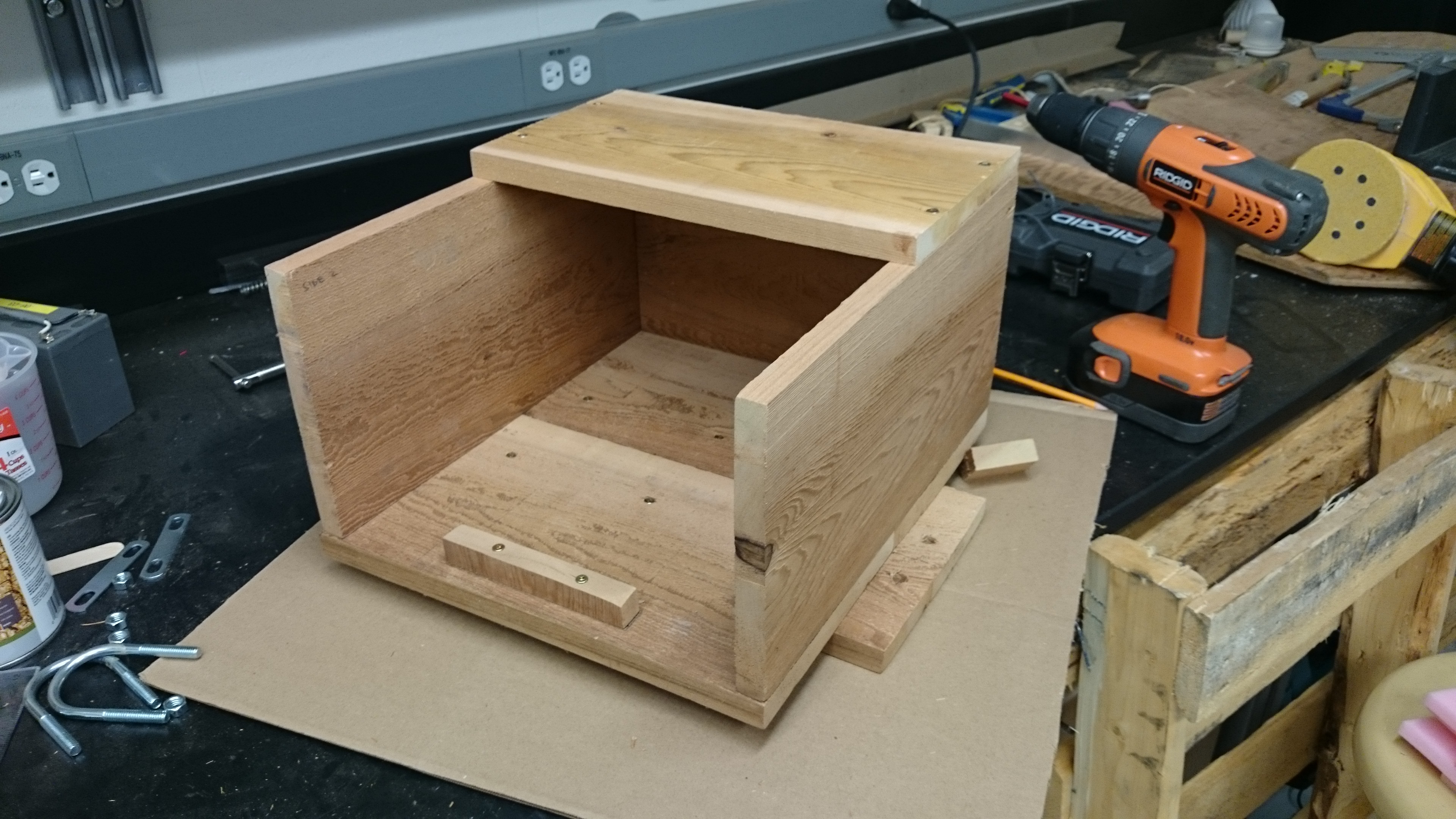
Yesterday, I built the aforementioned wooden shelter for the camera. This will act as a mount for the camera, protect the window from damage, dirt, and droplet build up, and reduce excessive heating from the sun. It was constructed using two 1″x8″x8′ pieces of cedar, some U-bolts, and assorted screws. I’m not a carpenter, and this was just a design that I thought up to solve a problem; there are probably far more elegant solutions! Below are some images from the build.


Very interesting article. Some nice DIY skills going on. Have you investigated/tested out possible condensation issues with the camera box? I just remember the club gopro occasionally let us down due to that.
Hope all is well in Canadaland 🙂
Thanks for reading, Ronan! I haven’t encountered any condensation issues in testing, but I’m aiming to minimize the chances of condensation occurring by including desiccant inside the case, and by housing the case itself in a larger wooden shelter (pictures of that to come) which will hopefully prevent rapid heating and cooling of the case due to sunlight. This should prevent large heat gradients between the case and air, which can cause condensation.
Seriously impressive work. Quite like that nighttime shot, looks like it’s working pretty well in the different light conditions!
Thanks! I’m definitely pleased with the quality of the images. Being able to chose what camera is used is the major benefit of building this yourself
Hi to the Man for All Seasons !
Thank you for the clear description of the camera, timer and the housing.
Well done on the design and on saving so much on the rig ! Your Celtic upbringing was not wasted on you ! Best wishes for the next stage of the adventure.
The folks back home.
‘Tonight on MacGyver!’ Great article Noel, loved the photo attachment for each step. Obviously you’ve got a good back-up camera. Best of luck with it all!
Hi Noel,
Great to hear from you. Like Joanne said, you didn’t have to go to Canada to build a weather station! That said some very interesting pieces of equipment particularly the 3D Ultrasonic anemometer. If you get a chance I’d like to hear the reason for it ie over & above the normal wind measurement. The camera; do I understand that it will take pictures at just set times, as opposed being triggered for unique events? And your window; how likely to “fog” up when fitted out on site? {just saw that question has been asked earlier}
Great record to date, and we all looked closely at the photographs of rock climbing & skiing!!!
Hi Frank, thanks for taking a look at the blog.
The main reason I am using a 3D sonic anemometer is because I want to observe the vertical component of wind or air flow over the glacier. While the standard propeller anemometer that I am also using will give me the mean horizontal wind speed and direction, the sonic anemometer can measure the air flow in 3 dimensions; two horizontal directions (x and y), and in the vertical (z).
As part of my research, I’m interested in measuring turbulent eddies over the surface of a glacier. These are simply rotating currents of air (generated by convection and wind shear), and they may be an important mechanism for transporting heat and moisture between a glacier and the atmosphere. By measuring the vertical component of these eddies (whether the air is moving up or down), and comparing it with corresponding measurements of temperature and moisture, you can determine the direction and the magnitudes of the flow of heat and moisture between the atmosphere and glacier. So as a simplified example, during one measurement the air is flowing downwards with a temperature of 5°C, and at the next it is flowing upwards with a temperature of 2°C. The flow of heat in this instance is towards the surface. For my set up, I’m making these measurements at a rate of 20 times a second (to capture all the rapid, small sized eddies), and averaging the values over 30 minute periods to get a general picture of the flow of heat and moisture. The technique is know as eddy covariance, and it’s more generally used for things like measuring the flow of CO2 over forestry etc. It’s rarely been used in glaciology, so here’s hoping!
As for the camera, it is set to take pictures every three hours, and is not triggered by any external events. To avoid condensation, I built an external shelter for the camera case, which I painted white. Basically, I wanted to make something similar to a radiation screen for a thermometer; the shelter protects the camera case from direct sunlight, preventing it from heating up too rapidly, which would cause a temperature difference between the air and the case, leading to condensation. Also, the camera rig itself does not produce much heat, as it is only switched on for a minute every three hours, so this prevents internal heating. I’ve recently collected the images from the camera (will post images soon), and there appear to have been no major condensation issues over the period.
Thanks again for reading. If there is anything else you’d like more info on, just ask or send an email.